
Construction of the Massive Fluidic Actuator Array
 |
Structure and Composition of the Massive Actuator Array (part of the system) |
To construct a scalable massive hydraulic actuator array, three major obstacle are overcome:
- Low cost and massive producible micro hydraulic actuator
- Low cost and massive producible micro sensor array
- Low cost and simple hydraulic driving structure
These progresses are elaborated in the following sections.
Capacitively Coupled Position Transducer Embedded Micro Actuator
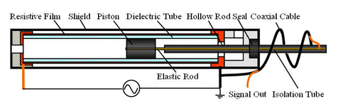
The major challenge to the ultimate use of a position transducer in digital clay is compactness of the system. Accuracy, bandwidth, longevity and other demands are not extreme, but all of these are also preferred. After a number of concepts were discussed, a transducer evolved that was particularly well suited for the actuators employed which consists of a glass tube with graphite pistons inside. The essentials of the sensor/actuator combination are shown in the figure below. The basic transduction principle is the variation of resistance in the circuit. Resistance was provided by a film on the outside of the glass tubing, deposited by one of several means. Sputtering of Titanium (Ti) was initially used. The pick off point was readily provided by the graphite piston on the inside of the tube, insulated from the film. Capacitive coupling between the film and the graphite requires the excitation of the sensor be AC. Important aspects of the implementation are the shielding of the signal, avoiding the effects of stray capacitance, limitation of current to drive an array of these sensors, and processing of the output signal to efficiently extract the measurement in the form desired for processing. One alternative closely resembles LVDT processing but other methods with superior traits are under development. The initial processing techniques achieve a linear fit with R^2 of 0.9999. For more details, please refer to the page of CCPT Sensing technology.
The capacitively coupled resistance transducer overcomes the major position sensing difficulties impeding the development of an expansive prototype of digital clay with extent and resolution of the order that is needed. The dependence on solenoid actuated valves was still an obstacle to compactness that will be discussed next.
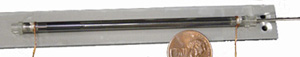
Structure of the CCPT Embedded Micro Actuator |
CCPT Embedded Micro Actuator |
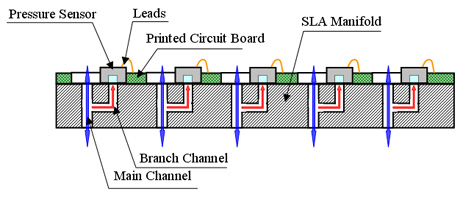
Pressure Transducer Mounting
One of the most daunting assembly tasks for the prototype is mounting the pressure transducers onto the manifold that accesses each cell’s pressure. This is not an essential limitation. It arises only because the packaging technology is not readily available for the prototype purposes. The sensor and signal conditioning are both provided by the Honeywell PS40 chip which is not available except in packaging for individual application. Following figure shows the layout schematically and shows a picture of the assembled sensor manifold.
 |
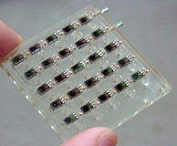 |
Pressure Sensor Manifold |
Pressure Sensor Array |
Fluidic Matrix Drive
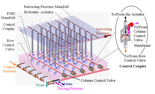
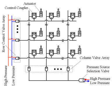
Actuation strategies discussed to this point have required two valves per actuator; hence an n×n array would require 2n^2 valves. While quite small miniature valves are available, they constitute the largest component of a single cell and the most expensive. The original expectation was that MEMS technology would be developed to provide the flow needed in a footprint of suitable size. While this may some day be the case it is far from certain, and a strategy based on current technology was sought. Inspiration from LED arrays, an analog fluid circuit was sought. It is displayed in the right figure.
The Fluidic Matrix Drive (FMD) concept still uses solenoid valves to couple computers to the control action. A great reduction of the number of valves is possible however, even with the 5x5 array prototype created which would require 50 valves when implemented in the previous fashion and only require 10 valves here. One set of valves controls the opening of a “control coupler” which is actually a second stage of the fluid valve. Opening a row control solenoid valve connects one entire row of actuators to the column control valves which can then move each actuator in that column. The key is to implement the control coupler compactly, inexpensively and effectively. Implementation of the control coupler is expedited, like a number of other detailed flow channels in this device, by stereolithography, a form of additive manufacture that uses a light sensitive polymer. The nature of the successful design here is shown in the figure at the top. It is formed in two levels by stereolithography with a thin membrane inserted between the layers.
Fluidic Matrix Drive Concept |
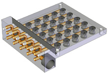
FMD Realization Design |
|
FMD Assembly |
5x5 Prototype & Test Results
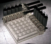
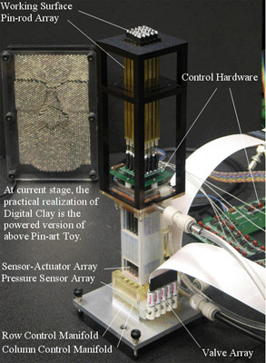
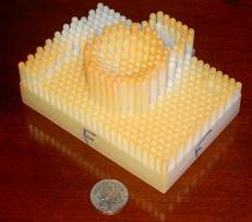
It is important for the reader to understand that the complex design of digital clay hardware described above and shown in the figure below, as well as the software and circuitry only alluded to work together. This will be done briefly with three types of tests that can be described and displayed with reasonable simplicity: surface generation, single cell speed control and array pressure measurement.
5x5 Prototype of Digital Clay |
|
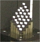 |
Surface Generation comes closest to capturing the entire purpose of digital clay in a single test. A slanted plane was generated and the tips of the rods were measured with a camera and processed digitally to verify the locations. |
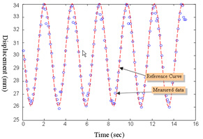 |
Cell Speed Control To test the velocity control ability of the proposed PWM flow control method, a single rod is commanded to track a sinusoidal trajectory. The measured results are shown in figure 15. The solid line is the commanded trajectory and the hollow dots represent the measured displacement. |
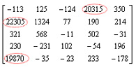 |
Pressure Measurements were tested by setting a weight on top of the digital clay surface with several patterns of cells supporting the weight. Since the lengths of individual rods are subject to some variation, a three point support tends to develop to support the weight as observed from the sensor readings shown left. |
 Example of camera artifact for resolution evaluation