Basic Principle
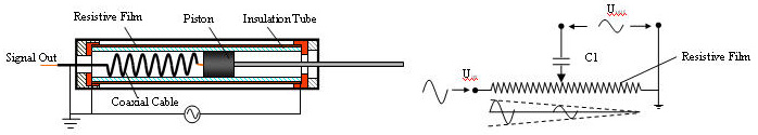
The basic working principle is depicted in the following figure. The basic transduction principle is the variation of resistance in the circuit. Resistance was provided by a film on the outside of the glass tubing, deposited by one of several means. Sputtering of Titanium (Ti) was initially used. Applying an AC excitation across the resistive film will deploy a linear distribution of amplitude of the alternating voltage along the film (Shown in the right of the figure under the resistive film). Coupled through the capacitance between piston (or Pick up head) and the conductive film, voltage amplitude on the piston reflects the position of the piston. The linearity depends on the uniformity of the film.
Capacitive coupling between the film and the graphite requires the excitation of the sensor be AC. Processing of the output signal to efficiently extract the measurement in the form desired has several alternatives. One alternative closely resembles LVDT processing but other methods with superior traits are under development.
 |
|
|---|---|
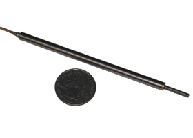
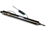
CCPT Sensor |
The Equivalent Circuit |
Signal Processing
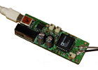
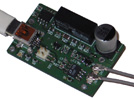
Sinusoidal excitation is commonly used for Linear Variable Deferential Transformer (LVDT). The CCPT sensor also can use a sinusoidal excitation scheme. By comparing the measured signal against the excitation signal, the displacement of the piston can be determined. Initially, a LVDT IC (AD698) was used in this work. Shown in the following left figure is an LVDT type Signal Conditioner is designed and implemented by H. Zhu.
 |
||
Sinusoidal Excited Signal Conditioning [Enlarge] |
LVDT Type Signal Conditioner [Enlarge] |
PCB Design File [Enlarge] |
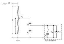
To lower the cost and improve the performance, a new excitation and signal conditioning technology is designed, which is introduced here. The conditioning scheme is depicted in following figure (left). Instead of applying a sinusoidal excitation voltage, a square waveform is applied across the resistive film. In the simplified scheme depicted in following figure, C1 is the capacitance between the piston the resistive film; C2 is the capacitance introduced when shielding the signal (to keep the integrity before being processed). C1 and C2 are both internal to the sensor. Rm is the impedance of the measurement system.
The variance of C1 is small and can be eliminated by, in a short period (< 0.00001sec), sampling the output both with and without capacitor C3. C1 usually will not change during above period. Values of C2, C3 can be calculated during calibration. Furthermore, C3 could be any component that can change the measurement impedance (e.g. resistor). Provisional patent on the square wave excitation technology has been filed sponsored by Sentrinsic, LLC.
 |
 |
|
Square-wave Excited Signal Conditioning [Enlarge] |
Square-wave Signal Conditioner [Enlarge] |
PCB Design File [Enlarge] |
This technique delivers the following advantages when compared to traditional LVDT signal conditioning:
- Significant reduction in the costs of the processing unit
- Simplified signal conditioning circuit
- Increased range of working bandwidth
- Reduction in the susceptibility of signal to noise
For more details, please refer to the Related Publications listed below.
![[Enlarge]](LVDT_SCH.jpg)
![[Enlarge]](LVDT_SC.jpg)
![[Enlarge]](LVDT_SC_PCB.jpg)
![[Enlarge]](SQSC_SCH.jpg)
![[Enlarge]](SQSC_SC.jpg)
![[Enlarge]](SQSC_PCB.jpg)