Kinematics, Dynamics, Control, and Simulationthis page last updated Oct 2003 |
|||||||||||||||||||||
|
|
|
|
|
||||||||||||||||||
DerivationsThe equations that describe the motion of the backhoe's links (swing, boom, stick, and bucket) are derived from the LaGrangian dynamic model. For a derivation of this model, as well as kinematic relationships, see the report on the backhoe Kinematics and Dynamics. See the document Kinematics for the initial derivation of the kinematic transformations between cylinder lengths, joint angles, base frame and local frames, geometric Jacobian, reverse displacement, and a digging simulation. The electrohydraulic proportional valve used on the robotic backhoe is modeled empirically from the results of Hardware-In-the-Loop testing. |
|||||||||||||||||||||
Simulation SoftwareIn order to capture all the significant dynamics of the
backhoe during a digging operation, the mathematical
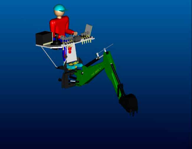
models have been programmed using In the backhoe model, functions have been written in a modular format to compute all the relevant variables, such as oil flow through valves, joint accelerations, control signals, hose compliance, bucket-soil interaction, displacement transformations, cylinder pressures, joystick dynamics, haptic forces, etc. Since the system has four degrees of freedom, most of the lines passing variables between each function block are four-element vectors. The input to the model is the desired trajectory of the bucket in the mind of the operator; the output is, among other things, the bucket position and orientation vs. time. Once a simulation has been run, the time history of each dynamic variable is then available for analysis. This model will be used as a design and analysis tool during the development of the Robotic Backhoe with Haptic Display. |
|||||||||||||||||||||
Open-Loop Simulation
|
|||||||||||||||||||||
 Open-loop valve commands |
 3D animation of joint trajectories (avi 1.6M) |
 ProE animation of simulation results (mpg 2.2M) |
|||||||||||||||||||
Trenching TrajectoryUsing a subset of the blocks from the model above, a program was written to compute the trajectory of each joint as the backhoe moved through a typical trenching operation. Input to the program was the desired digging dimensions defined over a sequence of 13 steps: reach, depth, unload position, etc. The output from the program was the position and angle of each joint versus time, which is illustrated in the plots below. |
|||||||||||||||||||||
 2D view of joint trajectories |
 3D view of bucket and wrist trajectories |
 3D animation of joint trajectories (avi 1.3M) |
|||||||||||||||||||
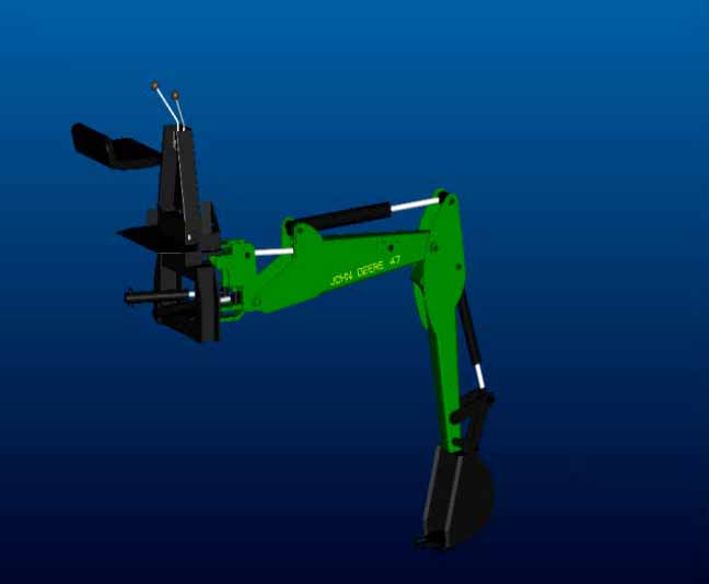
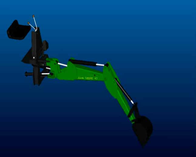
Trenching AnimationsUsing the results from above, the joint angle histories were then read into the modeling program (Pro/ENGINEER) and used to define joint drivers to animate the solid model. The movie files below illustrate the solid model animation. |
|||||||||||||||||||||
 trench_des1 (mpg 1.4M) |
 trench_des2 (mpg 1.5M) |
 trench_des3 (mpg 1.7M) |
|||||||||||||||||||
| These animations were generated using the desired trajectories. In the future, the solid model will be used to illustrate the output of the complete system simulation described above. | |||||||||||||||||||||
Joint Tracking SimulationThe plots below illustrate a trenching simulation. The plot on the left is the reference trajectory in the vertical x0-z0 plane, and the plot on the right illustrates the corresponding reference and model output in joint space. Although the plot on the right may seem trivial, considerable effort went into producing it. All told, the model includes 32 integrations per time step: three per valve, two per cylinder, two per link, and one integral control = 8 per degree of freedom x 4 degrees of freedom = 32 integrations per time step--i.e. a 32nd order model.
|
|||||||||||||||||||||
Model ValidationThe plots below compare the input/output data collected from the backhoe to the model prediction when the cylinders were given sinusoidal reference commands and an arbitrary digging trajectory, respectively. Click here to see video clips of the backhoe when the data was collected. Input is the voltage command sent to the valve and output is the measured cylinder lengths from the sensors. Distortion of the command signals is due to a combination of disturbances including unequal cap- and rod-side cylinder areas, vibrations, friction, and gravity. As can be seen, the model does a good job of simulating the backhoe's dynamics. |
|||||||||||||||||||||