|
|
|||||||||||||||||||||||||
|
|
|
|||||||||||||||||||||||
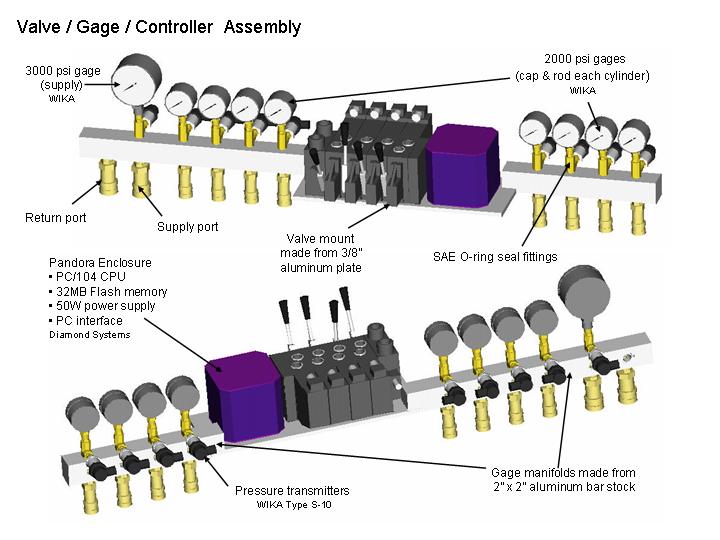
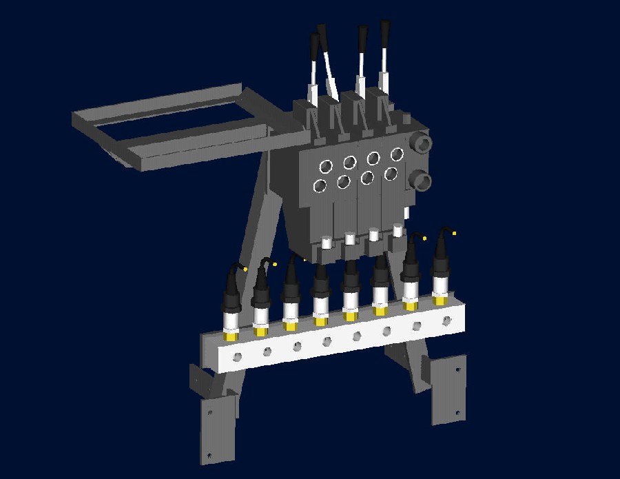
Valve Mount |
[2/2/04] |
||||||||||||||||||||||||
 |
 |
 |
 |
 |
 |
||||||||||||||||||||
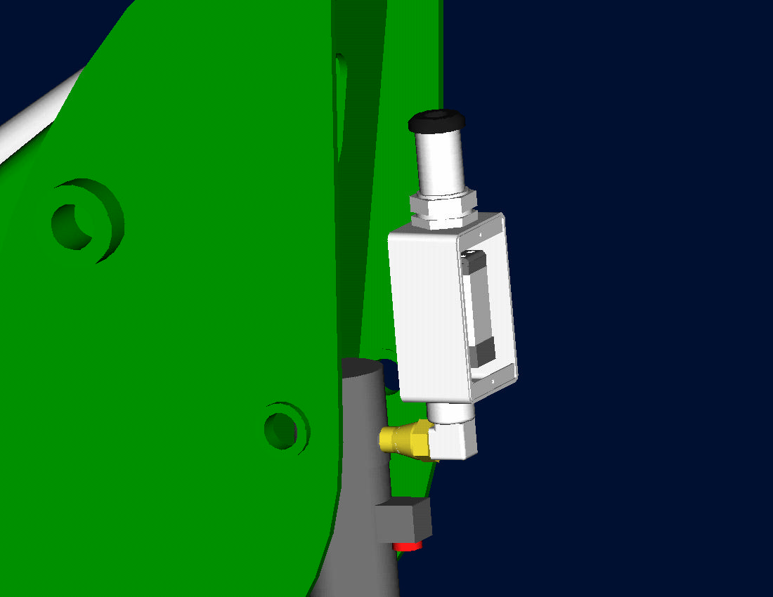
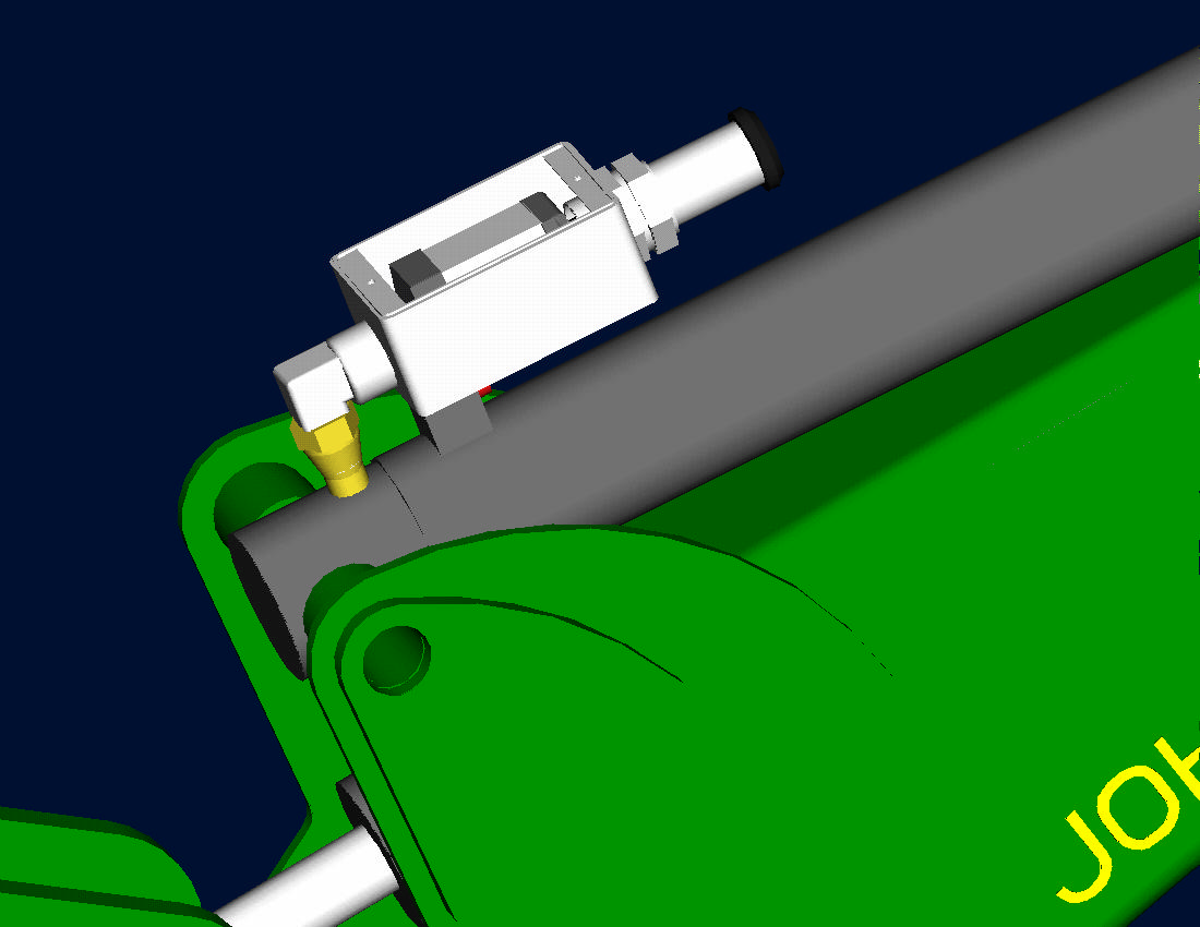
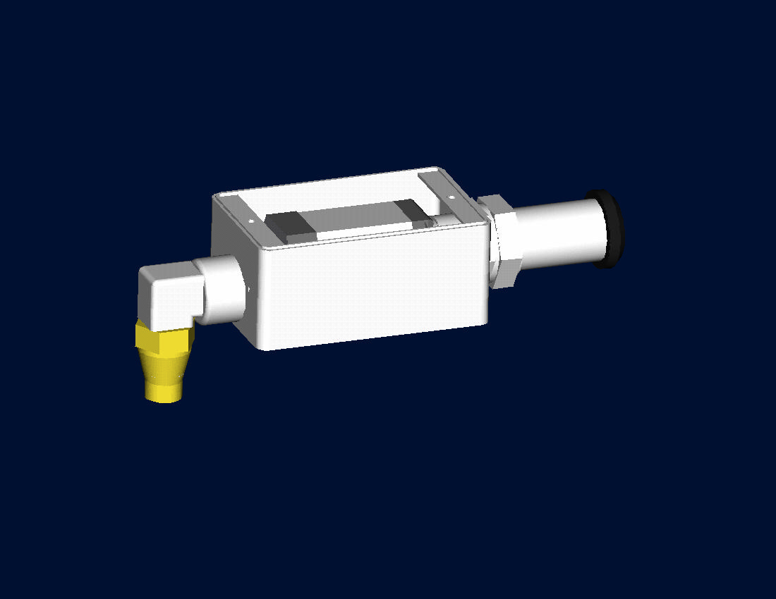
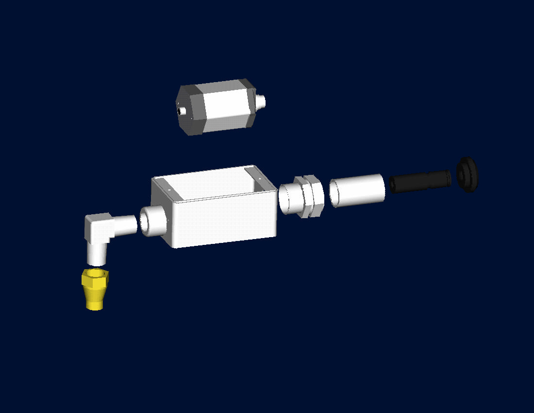
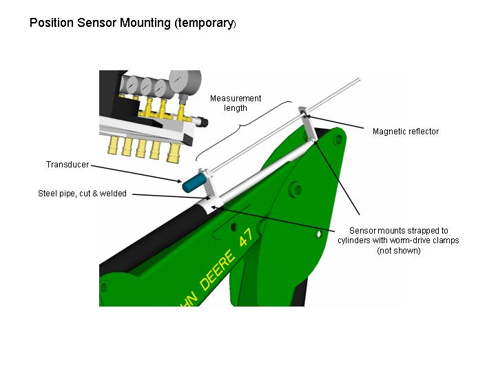
Sensor Mounts |
[1/25/04] |
||||||||||||||||||||||||
| Proposed design to mount the signal conditioning modules for the Balluff BTL-E cylinder position sensors. | |||||||||||||||||||||||||
 |
 |
 |
 |
 |
|||||||||||||||||||||
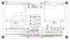
Power Supply / Junction Box |
[1/22/04] |
||||||||||||||||||||||||
| This box contains 12V and and 24V DC regualtors/converters, and also for routs signals between the valves, sensors, and target PC. | |||||||||||||||||||||||||
 initial concept |
 schematic |
 board layout |
 built |
||||||||||||||||||||||
|
|
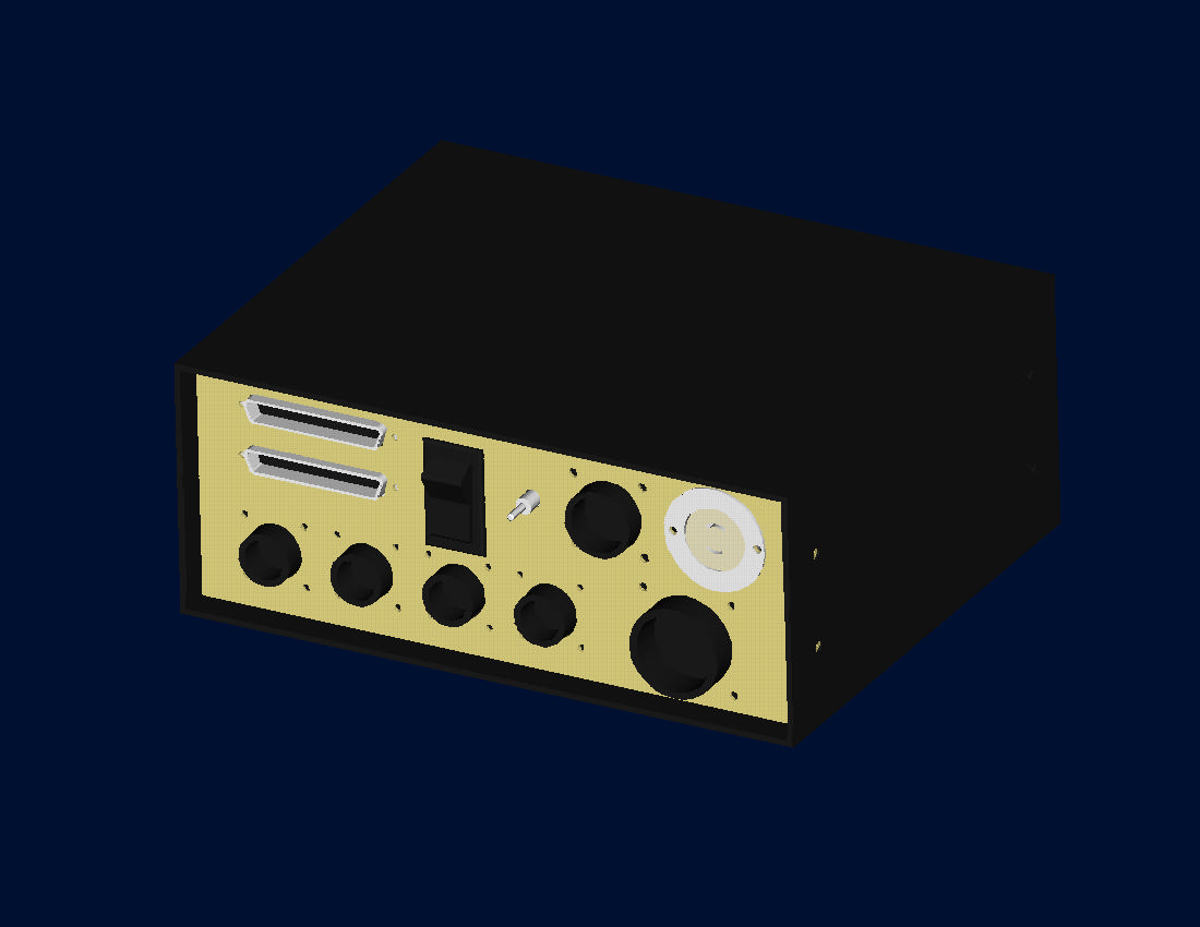
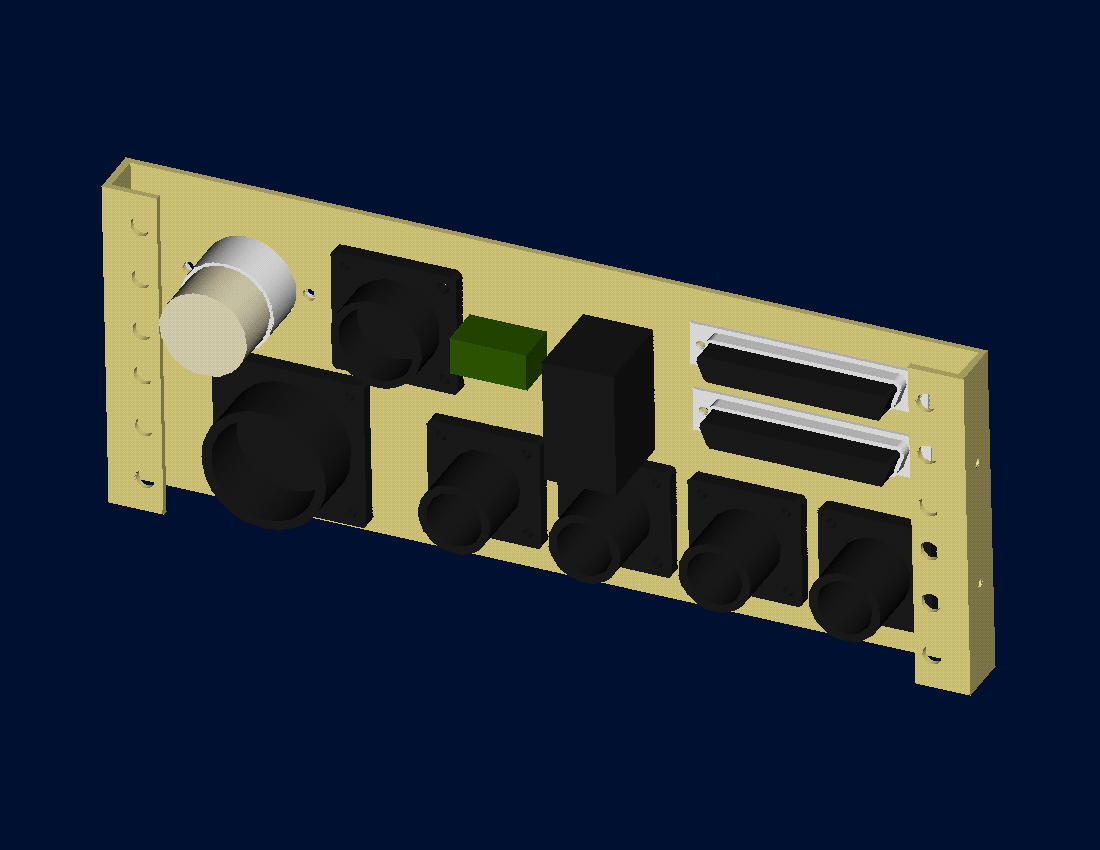 front panel cutouts |
||||||||||||||||||||||||
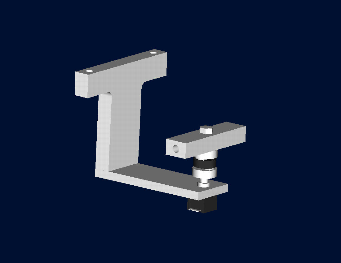
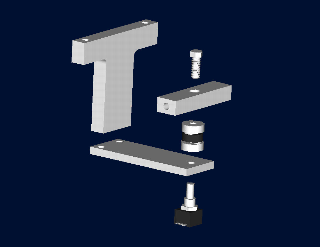
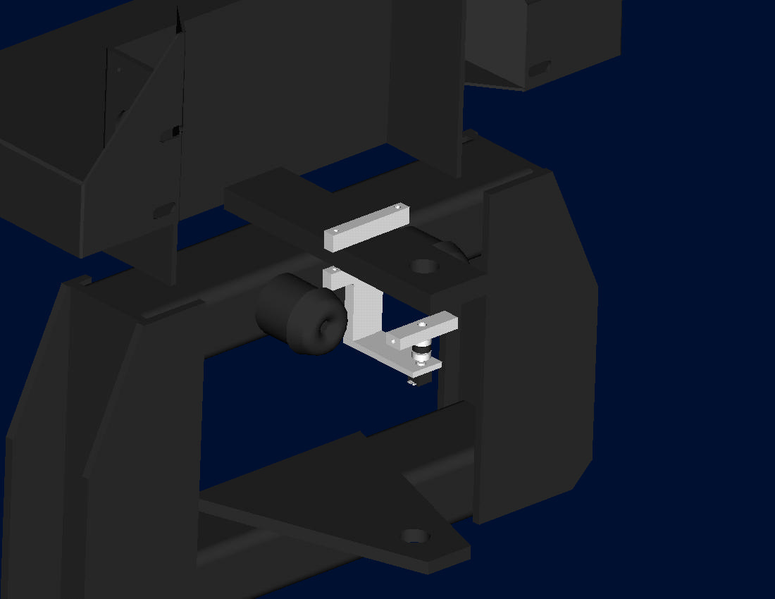
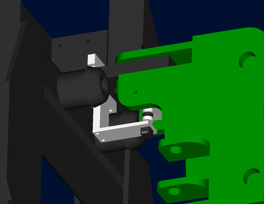
Potentiometer Mount |
[1/16/04] |
||||||||||||||||||||||||
| Planned design to mount potentiometer swing sensor for swing angle feedback. | |||||||||||||||||||||||||
 |
 |
 |
 |
||||||||||||||||||||||
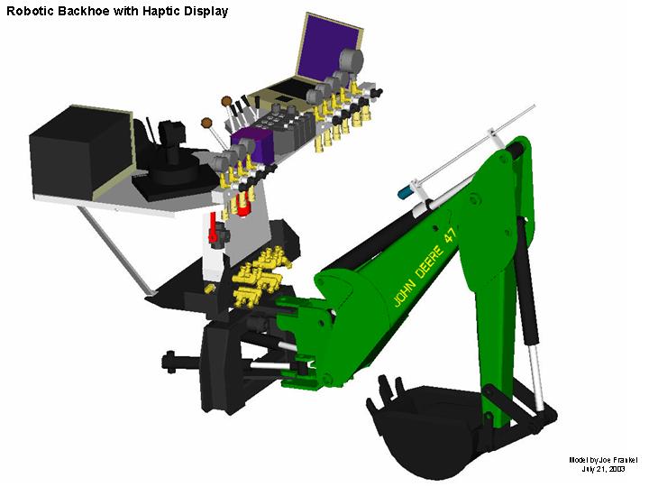
CAD Modeling |
[7/03] |
||||||||||||||||||||||||
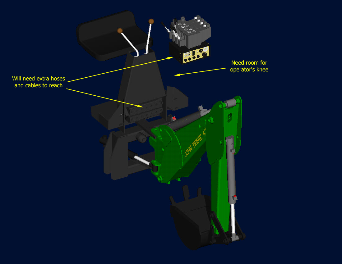
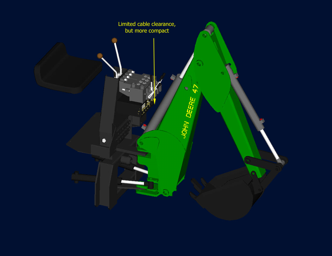
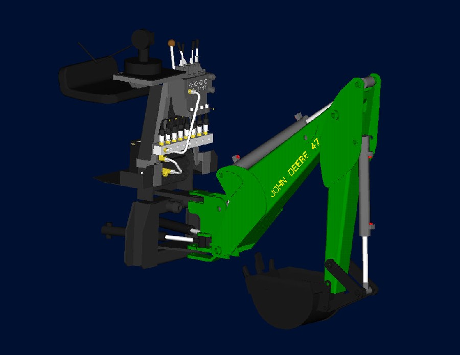
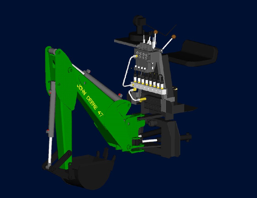
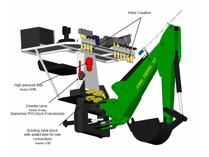
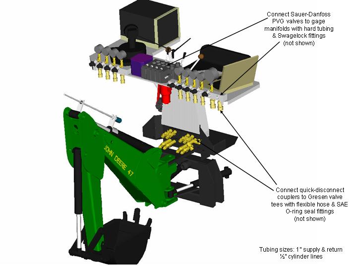
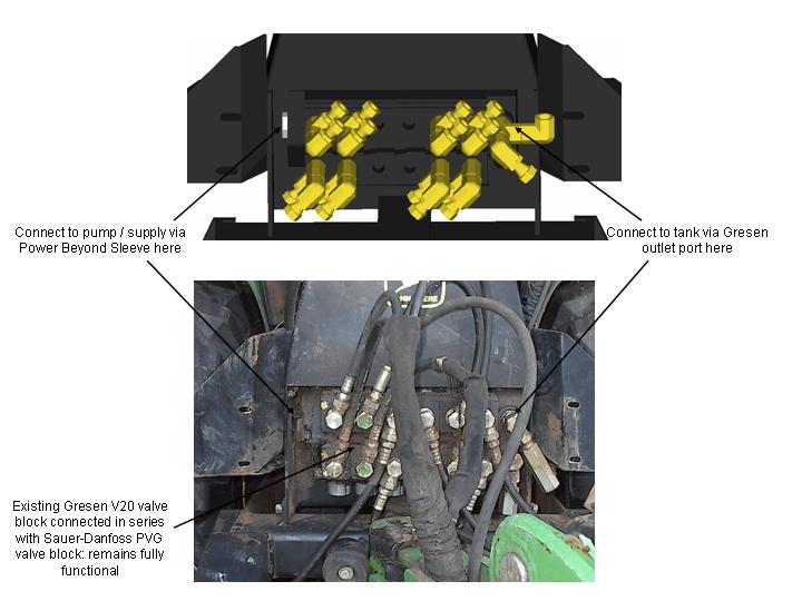
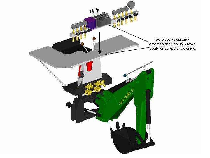
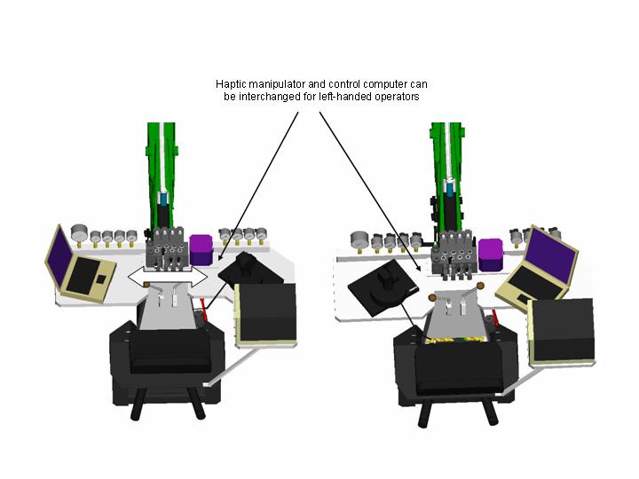
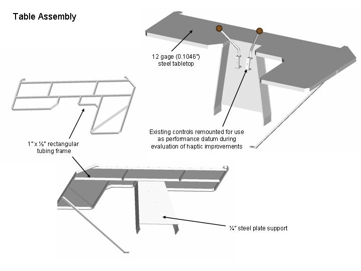
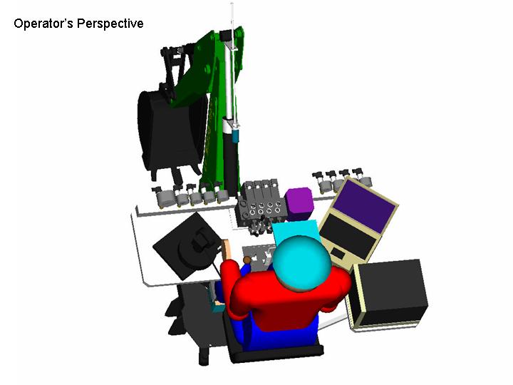
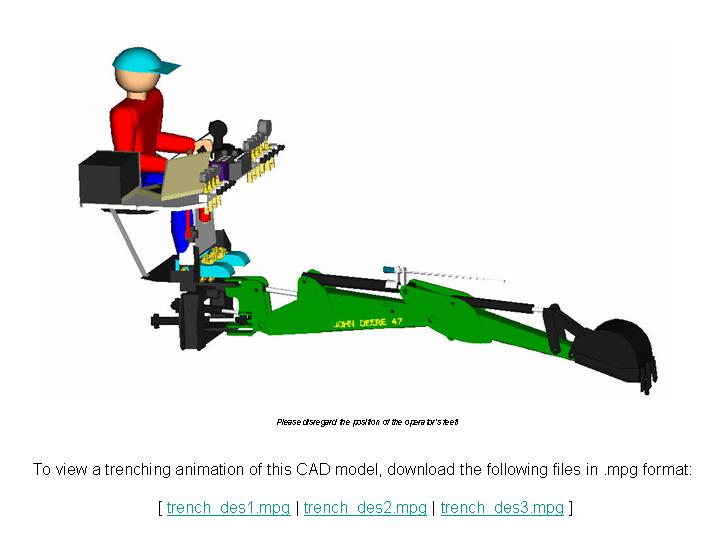
| The existing backhoe was first modeled and assembled in Pro/ENGINEER using the Mechanism Design Extension, which allows for the ability to generate animations by defining joint angles over time. The pictures below illustrate the design of the Robotic Backhoe with Haptic Display. | |||||||||||||||||||||||||
|
|
 |
 |
 |
 |
|||||||||||||||||||||
|
|
 |
 |
 |
 |
|||||||||||||||||||||
 |
 |
||||||||||||||||||||||||
| For a detailed parts list, see the Bill of Materials (xls 49K) | |||||||||||||||||||||||||
Hydraulic Circuit |
[7/03] |
||||||||||||||||||||||||
|
|
|||||||||||||||||||||||||
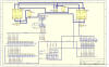
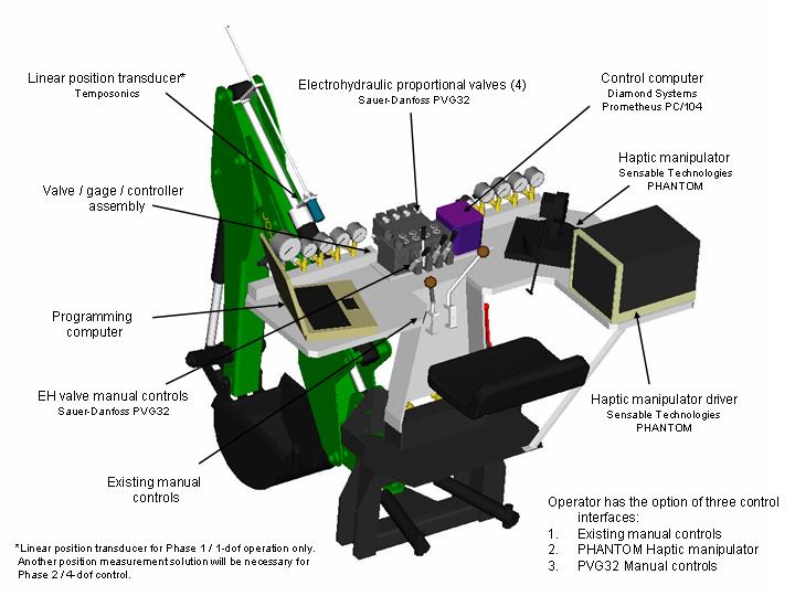
Signal Processing |
[7/03] |
||||||||||||||||||||||||
The picture to the right is a block diagram illustrating
the top-level logic of the Robotic Backhoe system.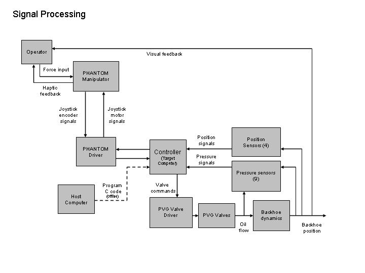 |
|||||||||||||||||||||||||
| These images may be also downloaded in the Design Overview (pdf 1.9M) | |||||||||||||||||||||||||
| To see a table comparing the features of potential controllers, see the Control System Options |
[8/03] |
||||||||||||||||||||||||