|
            |
Hardware In the Loop (HIL) Testing
|
HIL Background
|
| Hydraulic valves come in many varieties.
They can be spool-type or poppet-type, actuated manually, electrically,
hydraulically, or with a pilot line, they can be industrial or mobile,
open center or closed center, single stage or multi-stage, closed loop
or open loop, proportional or directional, pressure compensated, pulse
width modulated, linear or nonlinear, or possess a variety of the above
mentioned or other characteristics. In a typical hydraulic system, it is
often the valves that contain the most sophisticated mechanisms and
exhibit the most complex dynamic behavior, which can be difficult or
even impossible to model accurately based solely upon first principles.
When an accurate model of the valve is required, however,
the input-output relationships can be obtained empirically from a
Hardware-In-the-Loop simulation. Such a simulation involves connecting the
valve in question between a driving pump and driven load, which are each
carefully controlled in such a way to simulate either the normal, or a
hypothetical, working environment. The results of these simulations can then
be useful in design and prediction of the overall system performance.
In this project, a HIL simulation was
conducted to characterize the dynamic performance of the Sauer-Danfoss PVG32
electrohydraulic proportional valve. The results are given below. For detailed information on how the HIL
testing was setup and run, see the
HIL Operator's Manual. |

Hardware-in-the-loop system |
|
PVG32 Data Collected
| The PVG32 valve was installed into the HIL Simulator and
both sinusoidal and step response tests were conducted. The input was the control signal [V]
sent to the valve's driving electronics, and the output was the position of
the Temposonics linear transducer. The fixed sine tests were run between 1.0Hz and 8.8Hz at 0.2Hz intervals using an input
amplitude of 50% full signal to the valve. The magnitude [dB] and phase [o]
were averaged over a ten second interval at 1kHZ sampling rate for each
frequency. The magnitude and phase is plotted vs. frequency [Hz] in the
figure to the right. Because the desired linear model was to related flow rate
to the control signal, and position (ie integrated flow) was measured, the
magnitude data was multiplied by jw in the frequency domain and the
phase data was shifted by +90o before plotting. |

PVG32 Fixed-Sine Bode Plot |
|
Curve Fit Model
| At first, the PVG32 fixed
sine data was fit with a 3rd order linear model. However, the PVG32
possesses many nonlinear characteristics that would invalidate the
linear model over all but a tiny range of operating conditions. One of
these dominant nonlinearities is the steady state gain. It was observed
that the steady state gain was loosely related to the time averaged
input over a small period. This effect was modeled in Simulink, and the
results are presented below. More information on this
work is given in the
Fall 2003 presentation. |
|

3rd order linear curve fit |

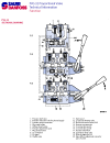
PVG32 schematic
also see the
PVG32 specifications |

Nonlinear valve model |
|
Step Response Validation
|
| The plots to the right illustrate the
PBG32 step response. The experimental data is compared with the model
prediction. As can be seen in the plots, the non-linear steady state
gain accounts well for the varying step sizes as compared to the linear
model. |

PVG32 step response |
|
Frequency Response Validation
|
| The plots to the right illustrate the
sinusoidal data taken from the PVG32, compared with the model
predictions for the same input signals. Although the model fits the data
fairly well, further work is needed in this area, to include a more
detailed description of the actual nonlinear dynamics. |

PVG32 sinusoidal time response |
|
|

