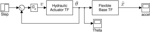
Block Diagram of the System
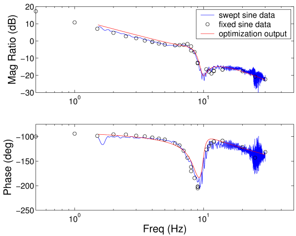
This figure shows Bode diagrams for the hydraulic actuator. The input is voltage and the output is angular position in degrees. The red line is the output of the model.
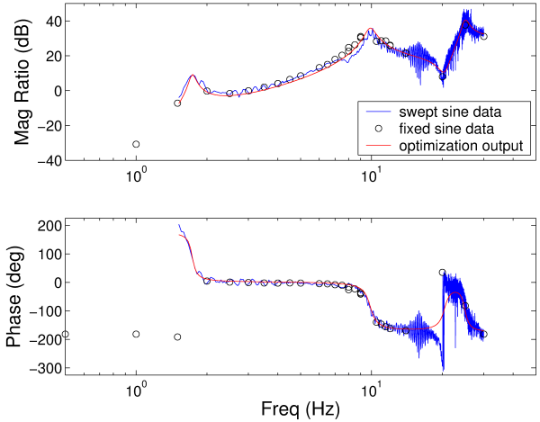
This figure shows Bode diagrams for the flexbile base. The input is angular position (the output of the hydraulic actuator Bode diagram above) and the output is angular position in degrees. The red line is the output of the model.