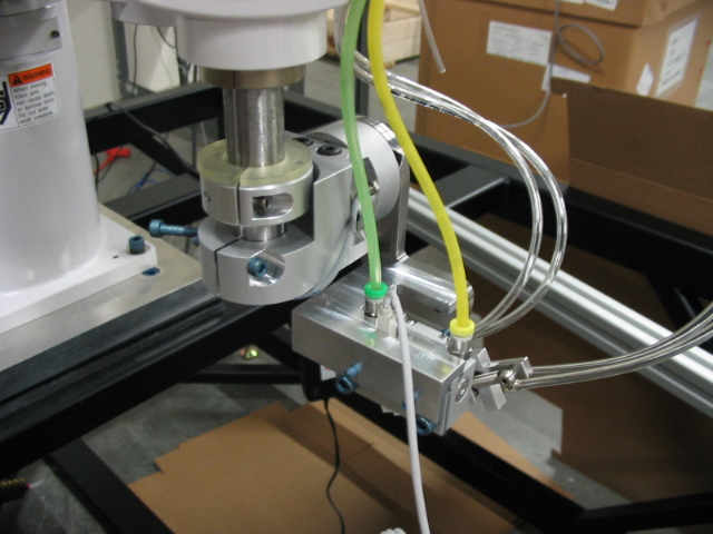
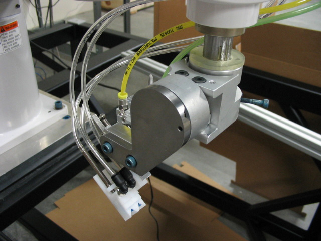
Project: SCARA Robot EEF: Bulk Tip Vacuum Gripper for Rainin Instrument, LLC, July 2006
This prototype end-effector was used for assembly tasks in a high speed robotic work cell. It was designed using Autodesk Inventor. The features of this tool include: easily detached from quill mount (magnetic coupling), vertical compliance during both part pickup and part placement, ability to pickup a variety of product with v-block vacuum pickup, ability to assembly two parts per cycle, and modularity (number of v-block asssemblies expandable to increase number of parts assembled per cycle).
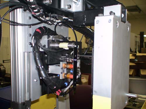
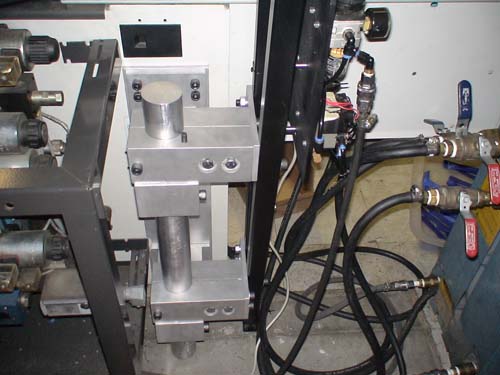
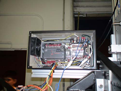
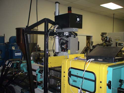
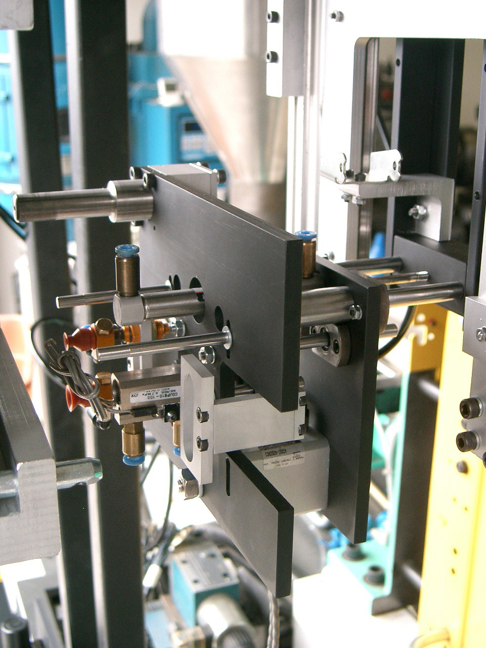
Project: Injection Molding Machine Tending Robot for Bojo, Inc., May 2006
This project is an example of hard-automation, an automated machine serving a specific task. The task here is to place a steel insert into the cavity of the mold so that a part can be overmolded. This project was for my final year senior design project and I worked on it with one other classmate over two semesters. The motion of the pneumatic actuators is sequenced by a Keyence PLC. Sensors used include fiber optic, proximity, and vacuum pressure. Both automatic operation and manual step-by-step operation is available for the operator.
MPG Clip: automatic cycle. (the lag between movements is because the machine had just been setup and was yet to be used for production. It was being tweaked.)
MPG Clip: manual cycle close-up.
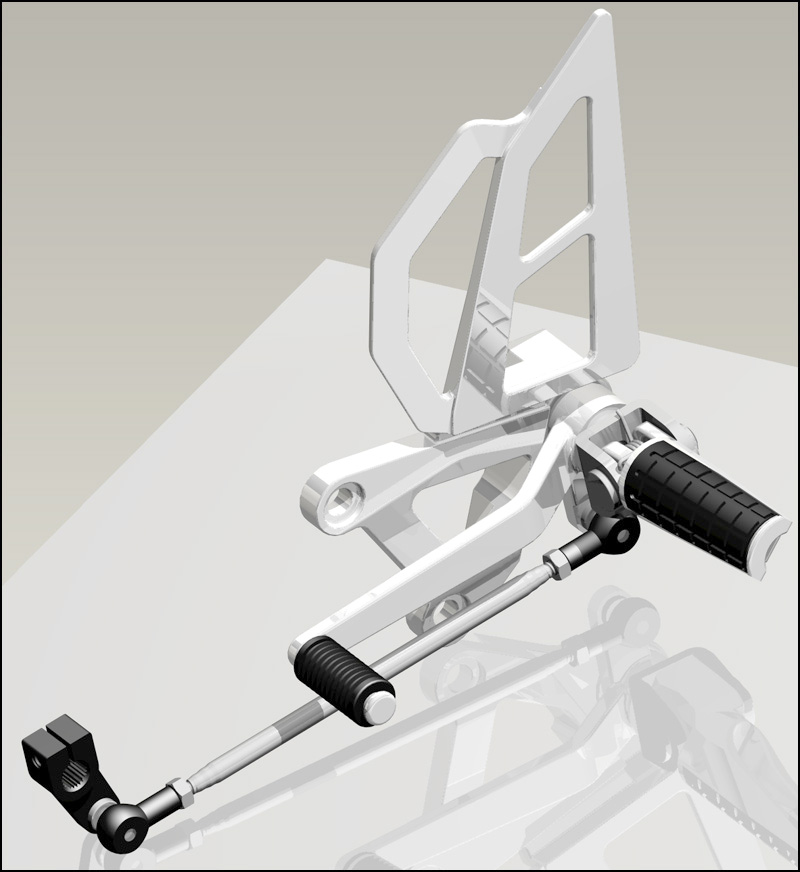
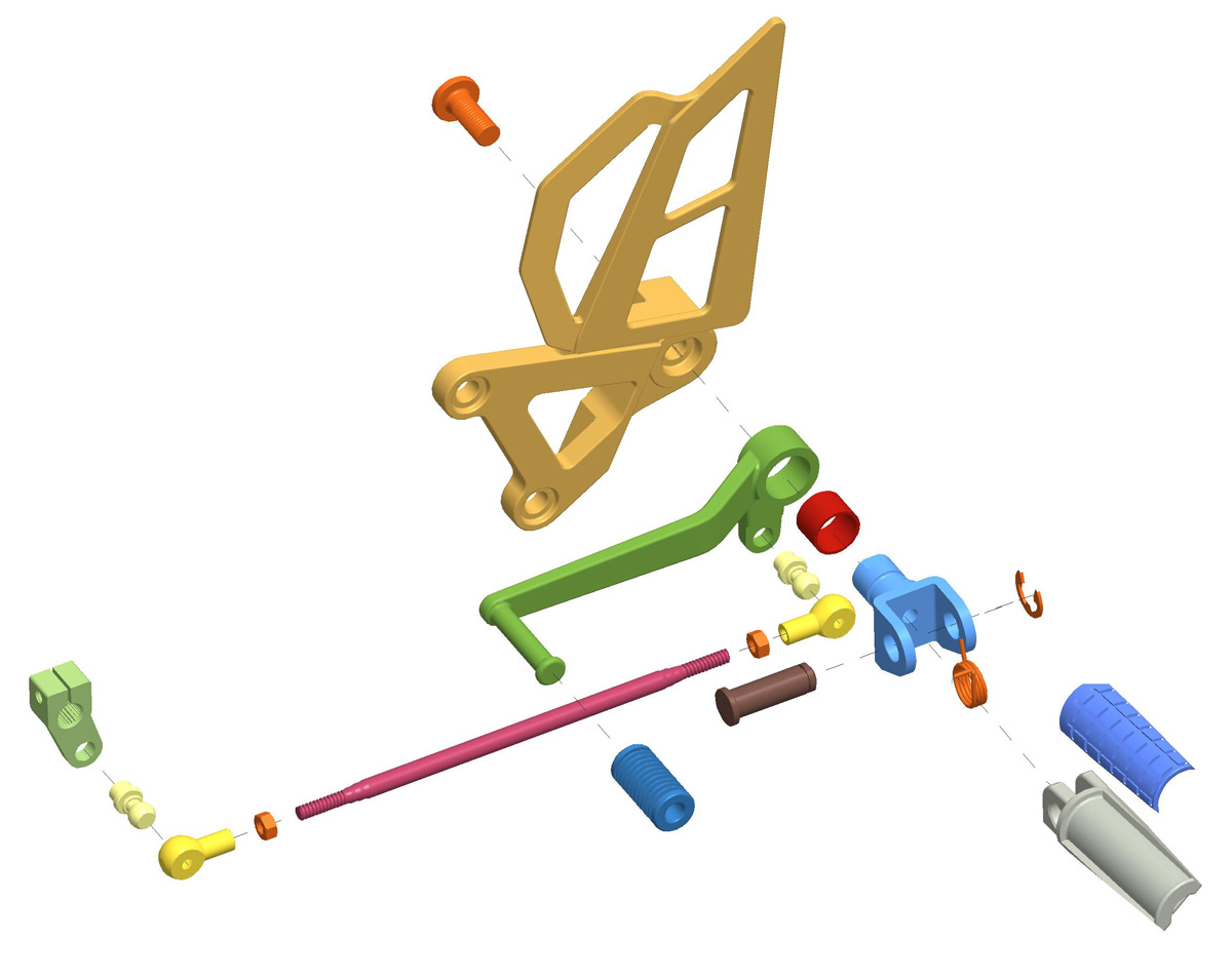
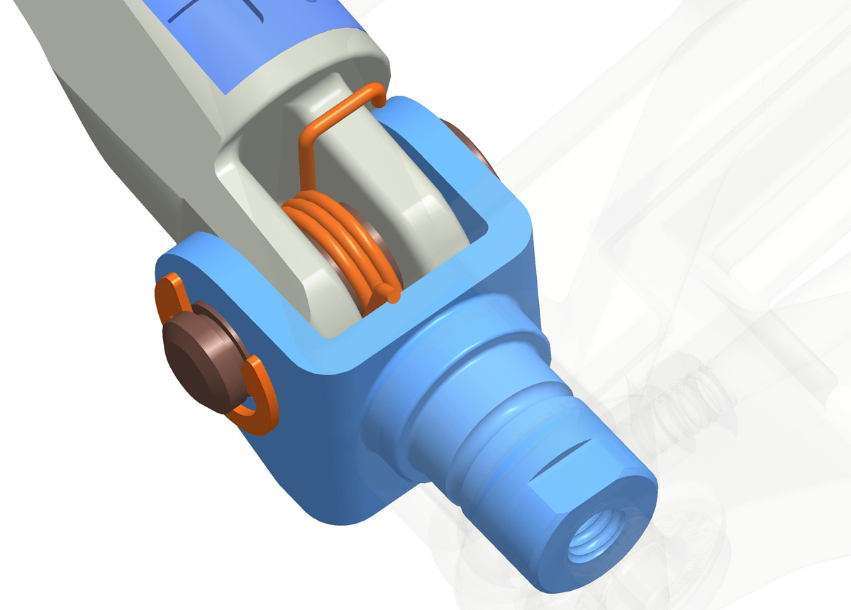
Project: CAD + FEA model for a 1998 Kawasaki Ninja zx7r Rearset, May 2005
This is a very accurate CAD representation of the rearset assembly on my motorcycle using Pro/E. After completing the model I proceded to use Mechanica to conduct FEA studies, considering stress concentrations under just static loading. As I discovered, FEA of a multi-body assembly is very challenging and time consuming, requiring use of Pro/E functions called contact regions where surfaces mate.
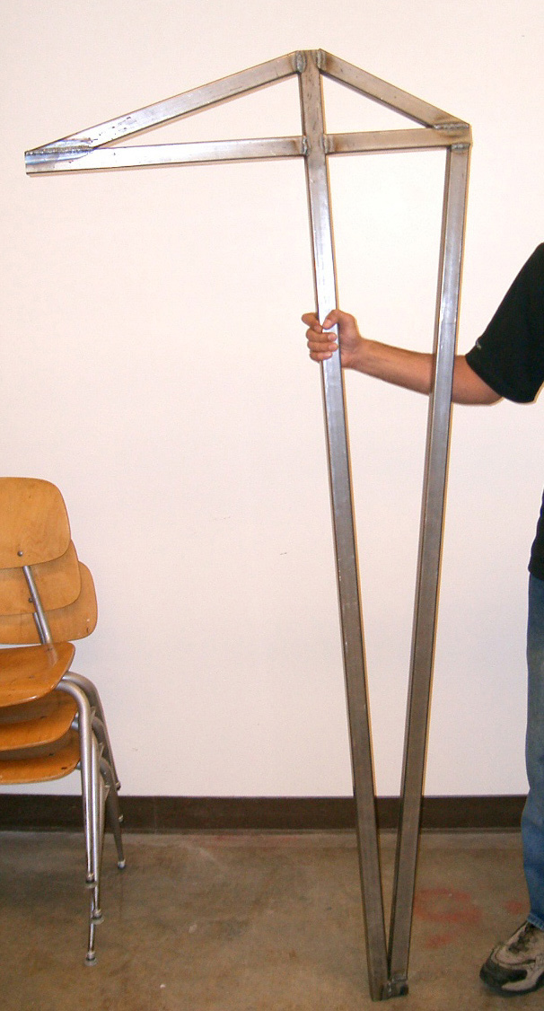
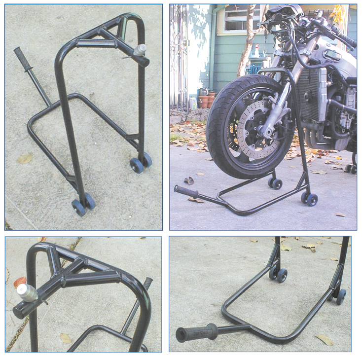
Project: Rearstand for 1998 Kawasaki Ninja zx7r, December 2003
A frontstand is useful for disassembly of motorcycle frontends, including the front forks. I designed this front stand with 1" OD 1018 steel tubing in Solidworks. The tubes were bent using a manual draw-type tube bender and were MIG welded.
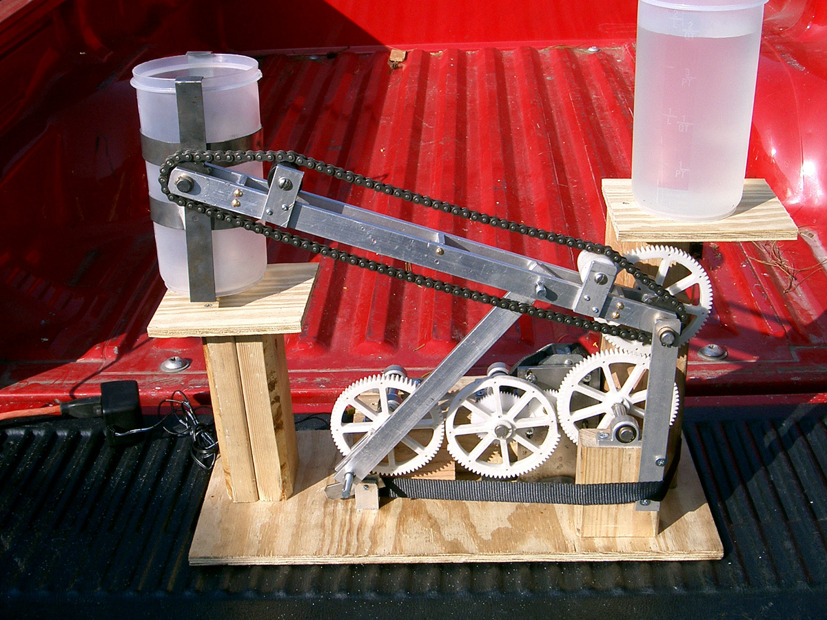
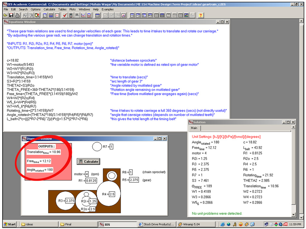
Project: Four-stage Four-bar Planar Mechanism for Transporting Liquid, December 2004
While the function itself (pouring liquid) of this planar mechanism may not be very exciting or even useful, what is unique about this mechanism is the fact that the function is achieved using a gear train and not fancy electrical sensors for timing. A mutilated gear allowed the two parts of the gear train to operate independently. Based on a DC gearmotor for input, the gear train was designed using Engineering Equation Solver and the time to translate the container from start position to final position and the time to rotate the container were optimized to minimize risk of spillage.
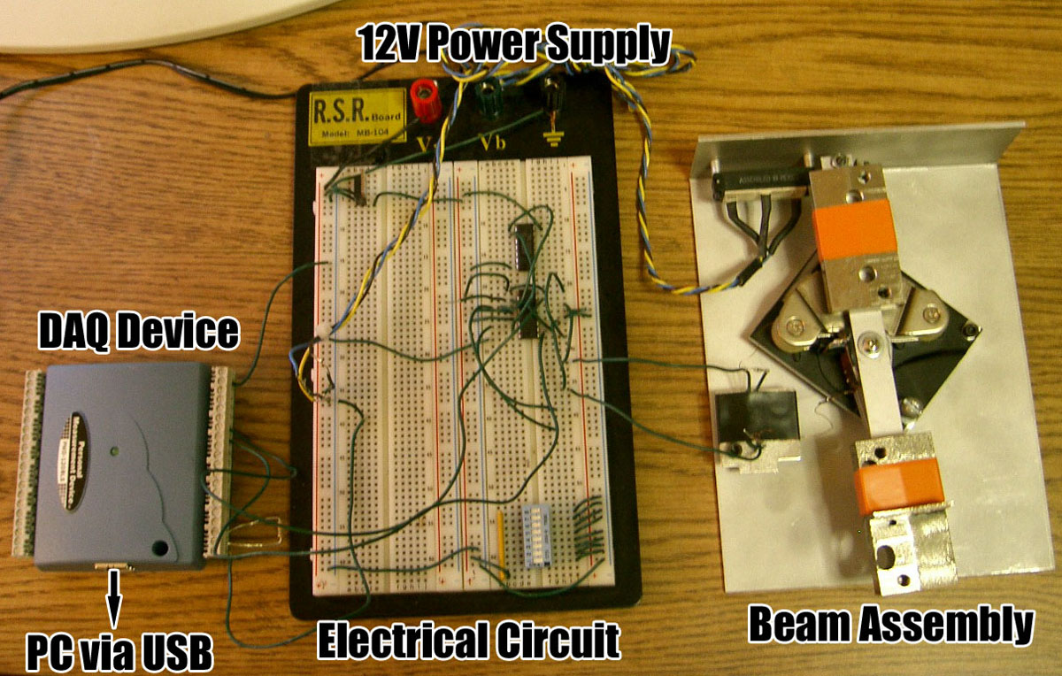
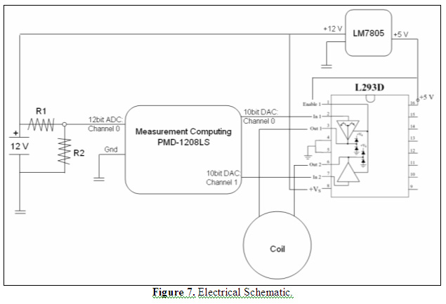
Project: Simple Labview Position Control Feedback Control System, December 2005
This simple project demonstrated use of feedback control using LabView. It is a single input-single output position control problem. The actuator is a voice coil from a hard disk drive and the sensor is a precision linear potentiometer. A PID subVI supplied by the Control System toolbox was used. The closed loop system, although stable, had unacceptable transient performance due to hardware limitations. The voice coil was driven using PWM generated in the regular windows LabView environment which is not well suited for dedicated tasks with strict timing requirements such as pulse generation (LV Real Time is what was needed...).