Block Diagram of a Mass Damping Control
System with a Pole Canceling Compensator
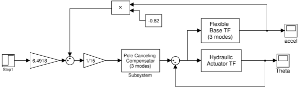
This figure shows where the pole canceling compensator is to be placed in the block diagram of the SAMII control system with acceleration feedback.
This figure shows where the pole canceling compensator is to be placed in the block diagram of the SAMII control system with acceleration feedback.
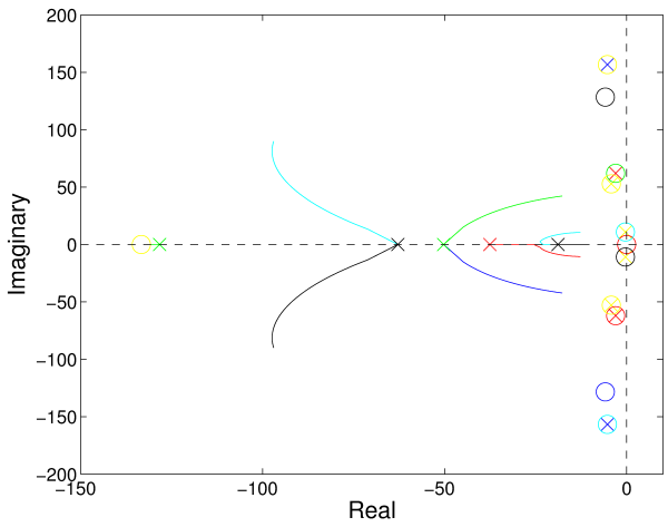
This figure shows a root locus for the system with a pole canceling compensator. The circles with X's in them are canceled poles. Three pairs of poles are canceled by the compensator and one pair is canceled naturally by the interaction between the hydraulic actuator and the flexible base.
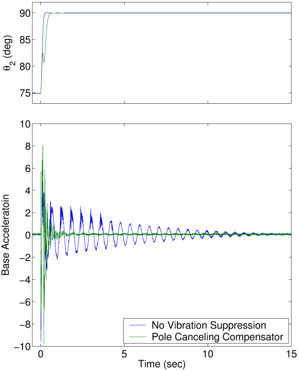
This figure shows simulated results for a step change in angle with and without the pole canceling compensator. The pole canceling compensator is effective and reducing the vibration resulting from this movement. This improvement in vibration response for the system is primarily the result of changing how the step change in angle is input into the system, as can be seen in the top sub-figure.
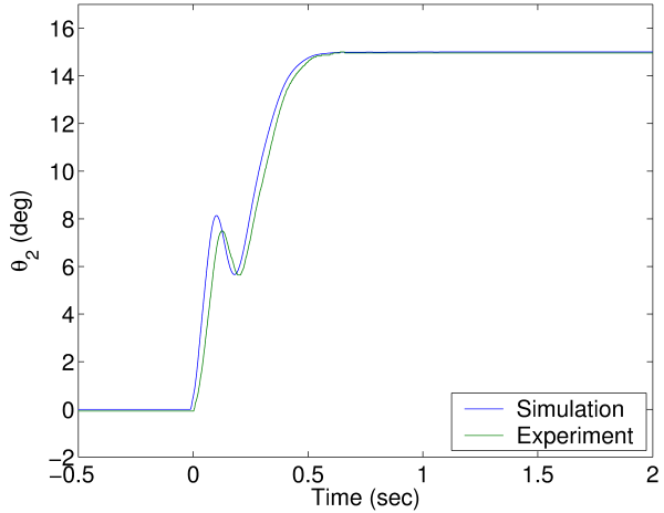
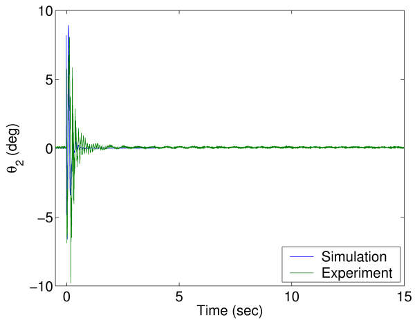
This figure compares experimental and simulation results for joint angle vs. time.
This figure compares experimental and simulation results for base acceleration vs. time. Note that this is the same settings for the time axis as is shown in the simulation plot above for systems with and without the pole canceling compensator.
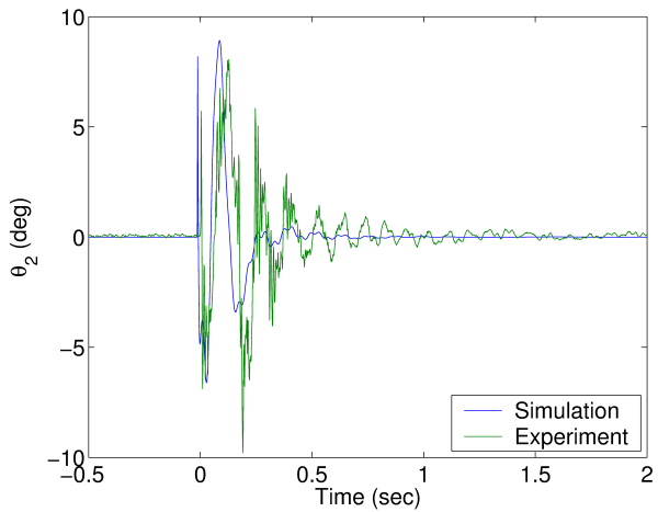
This figure zooms in on the plot above. The agreement between simulation and experiment is not quite as good as the plot above seems to show when we zoom in.
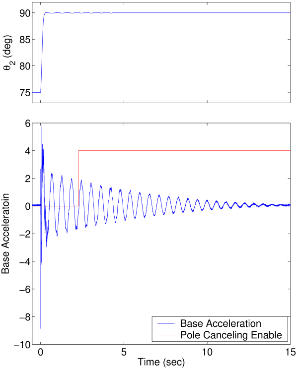
This figure shows that the pole canceling controller is not able to reject a vibration disturbance. The joint is initially moved with the pole canceling compensator disabled so that the base vibrates. Then the pole canceling compensator is enabled and the vibration continues essentially unaffected.