Unmodified System
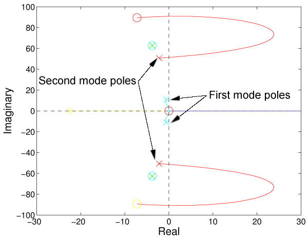
This figure shows the root locus for the unmodified system. Note that as the gain for the controller is increased, the poles from the first mode of the flexible base are moving to the left (increasing dampig) while the poles from the second mode are moving to the right (decreasing damping). While damping is being added to the first mode, it is being subtracted from the second mode. As a result, the second mode becomes unstable.
This figure shows the root locus for the unmodified system. Note that as the gain for the controller is increased, the poles from the first mode of the flexible base are moving to the left (increasing dampig) while the poles from the second mode are moving to the right (decreasing damping). While damping is being added to the first mode, it is being subtracted from the second mode. As a result, the second mode becomes unstable.
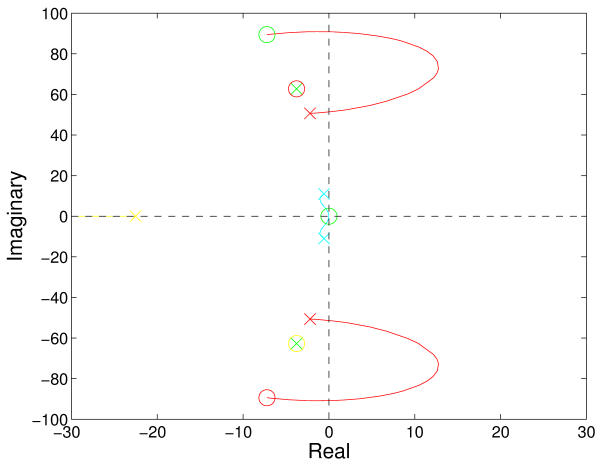
This figure shows the root locus for the system with the feedback accelerometers replaced with position sensors. This change eliminates two zeros at the origin, but does not solve the main problem of the poles from the first and second modes moving in opposite directions. Note that using accelerometers instead of position senors was one of the suspected causes of instability.
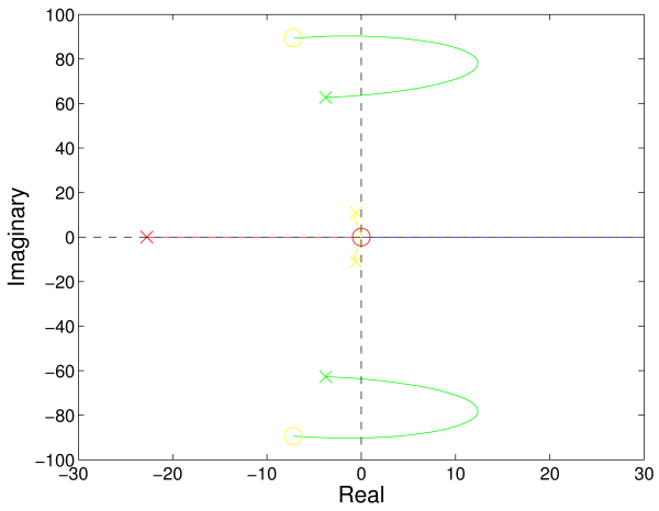
This figure shows the root locus for the system with second order dynamics removed from the actuator model. This change forces the actuator model to act like a velocity source, eliminating another suspected cause of instability.
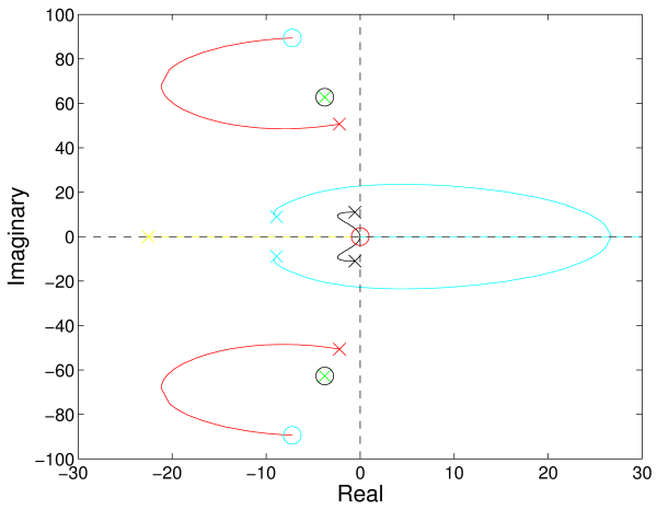
This figure shows the root locus for the system with a low-pass filter on the feedback accelerometer signal. Note that for the first time, the poles from modes one and two are both moving to the left with increasing gain.