Improved digital control of the clutch's slip torque
Initial efforts to control the redesigned clutch's slip torque through feedback of the built in torque sensor proved promising, but limitations in software only allowed a digital control frequency of ~50 Hz. This, compiled with a slow second order current response of the unipolar power supply used, proved to hurt performance. Several hardware and software changes were made with a desire to further increase performance.
For starters, the unipolar linear power supply was replaced with an Advanced Motion Controls Brush Type PWM Servo Amplifier (25A8E) and corresponding power supply. The new bipolar amplifier was set to torque (current) mode. Implementation of new control code utilized a dSPACE DS1102 with Simulink's Real Time Workshop. This allowed controllers to be designed within the Simulink domain and the code to be directly compiled & downloaded to the dSPACE micro-controller. Digital sampling rate was set to 1Khz, a large improvement over the 50Hz achieved with LabVIEW. For recording data, LabVIEW was used to sample at 10 kHz (PCMIO 16-E4) the analog signals from the dSPACE controller and clutch's torque sensor.
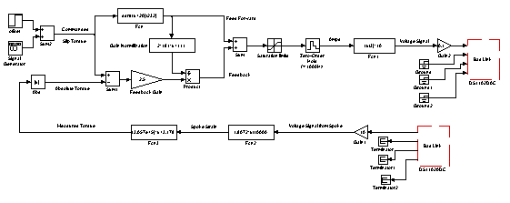
The clutch's controller consisted of a nonlinear feed-forward term along with an additional term based on proportional feedback control. Because the clutch's gain (torque / current) is dependent on the excitation range, an online gain normalization was added to allow one controller gain to work with all excitation ranges. Current excitation saturation limits were set to prevent both the current level from dropping below a minimum required to hold the clutch's armature plate close to the magnet (minimize air gap) and from over excitation. The Simulink diagram can be reviewed in Figure 1.

Figure 1 (click on the figure for a bigger image)
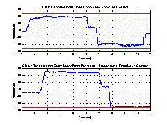
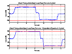
Because a clutch can only reseit motion and can not generate torque, the tests consisted of commanding a slip torque while the clutch was forced to slip in both directions, hence bidirectional torque measurements. Figure 2 (125 in-lbf slip commanded) & 3 (200 in-lbf slip commanded) shows the effectiveness of the clutch to generate the commanded slip torque with only the open loop feed-forward term and with both the feed-forward & feedback control. Though a more accurate feed-forward model could improve the open loop performance, it was found that the clutches change from day to day making an extremely accurate feed-forward term prohibitive. In addition, the slip torque fluctuations as the clutch rotates through its travel. It is evident that feedback control improves the capability of the clutch to track the commanded slip torque.

Figure 2 (click on the figure for a bigger image)

Figure 3 (click on the figure for a bigger image)
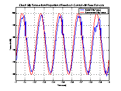
Next, the commanded torque was defined as a shifted 5Hz sine wave, fluctuating between 100 and 200 in-lbf. It can be seen in Figure 4 that the clutch was capable of tracking the general form of the commanded slip torque. It should be reiterated that the clutch can only produce resisting torque. If the operator forcing the clutch does not produce enough torque to slip the clutch it will only resist the input torque, which is less then the slip torque. By inspecting Figure 4 it can be hypothesized that the jaged spots at the peak of the wave are a result of the operator not supplying enough torque to make the clutch slip.

Figure 4 (click on the figure for a bigger image)
Future work
From this point forward, additional clutches with built in torque sensors are to be integrated in PTER. Clutch control efforts will continue not with the dSpace, but rather with the control hardware PTER is going to utilize (QNX).
Return to Main Haptics Page


