Flexible Motion System Control
▼ Project Overview▼ ▼ Robust Estimation▼ ▼ Flatness-Based Control▼
Project Overview
Project Objective
To improve the utility and performance of flexible motion systems by enabling high-speed precision manipulation through advanced control methods.
Motivation
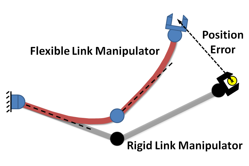
Flexibility is often an unavoidable limitation when large-workspace high-speed manipulation is required. Flexible systems are prone to undesirable vibration. To mitigate these effects, they are often operated well below their capable operating speeds. This not only limits the efficiency of these systems, but also hinders their functionality, as dexterity, performance, and workspace size are sacrificed for accuracy and reliability.
Examples of Flexible Motion Systems
Since their initial introduction in the 1960s, significant advancements in industrial manipulators have been made. However they are still, with relatively few exceptions, powered by electric servomotors and rely primarily on internal sensing to determine their position and orientation in the workspace. Thus, in order to reliably position the end effector, the links which comprise the robot must be rigid, and the joints where actuation takes place are designed to exhibit very little compliance. These conditions are obtained through structural design employing strong, heavy materials and reducing the link lengths. Ultimately these design requirements lead to large powerful motors and drives in order to actuate these massive structures. These motors and drives not only require more energy to operate but come with larger initial costs. Since a larger percentage of the torque produced from the drive is reserved for motion of the structure itself, less is allotted to the acceleration and motion of the payload, resulting in reduced payload capacities.
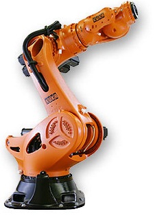
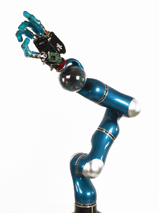
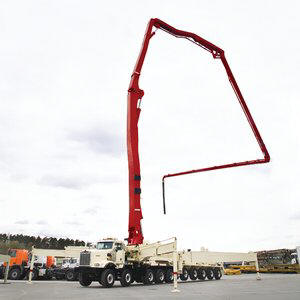
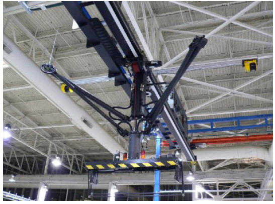
(a) Industrial Manipulator (b) Lightweight Manipulator
Figure 1:
Traditional and Lightweight ManipulatorsExamination of the current products (Figure 1(a)) of four major industrial robot manufacturers, Fanuc, ABB, Kuka, and MotoMan including twenty nine speci c robot models sampled from low to high payload capacity lines of each brand indicates that most operate with payloads less than 10% of the total manipulator mass, a significant portion of which require payloads of 5% or less. The higher ratio robots shown in Figure 2(a) are found in heavy duty manipulator categories with payload capacities greater than 150kg, which are a significant minority of the total market. Workspace size is also sacrificed for the sake of rigidity, as increases in link stiffness are necessary to prevent loss of accuracy and repeatability under static deflection and vibration during motion. As shown in Figure 2(b), increases in workspace size result in increased mass. This excess mass means that these systems carry significant amounts of energy when in motion, and any collision with the environment or operator can certainly be destructive, if not life threatening. Therefore all human interaction with these manipulators is strictly prohibited and safety barriers are erected to separate the operators from the robots
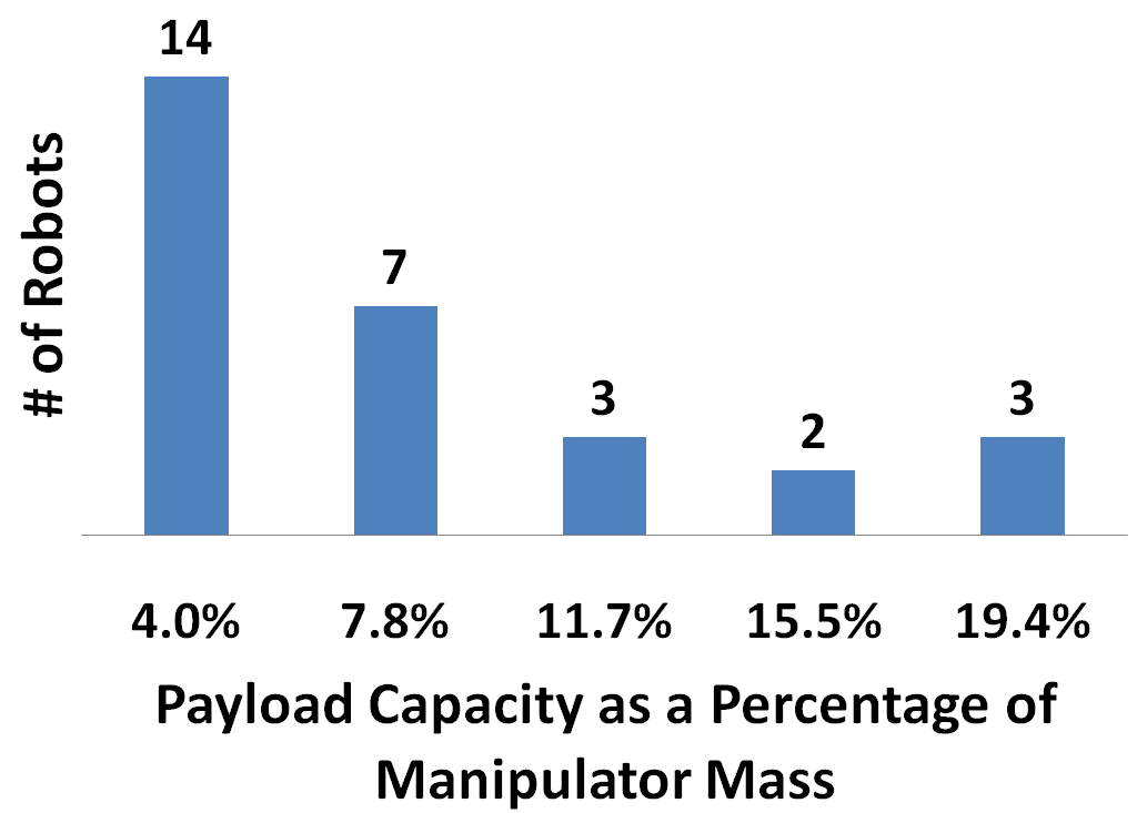
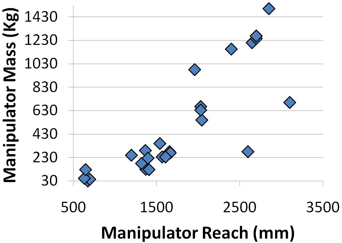
(a) Comparison of Payload/Total Manipulator Mass Ratios for Standard Industrial Robots (b) Comparison of Reach to Total Manipulator Mass
Figure 2:
A Survey of Commercially Available Robotic ManipulatorsReducing the mass and extending the reach of these robotic systems improves the system performance by allowing more of the power generated by the motors to be transformed into motion of the payload rather than the structure itself resulting in greater accelerations and reduced cycle times. Extended reach also enables greater utility as workspace size increases allowing manipulation of larger objects and promoting more cost efficient automation solutions. With lighter weight components, efficiency also improves, and therefore smaller motors and drives can achieve the same performance metrics, reducing the need for expensive high performance actuators and energy costs. While most industrial manipulators are certainly too heavy for mobile applications and require large sturdy mounting platforms, light weight manipulators have seen use in many applications where total mass is limited. Examples include explosive ordinance disposal robots, space robotics, and many others. By reducing the mass of the manipulator the system is made less rigid and more compliant resulting in a manipulator more suited for “soft” robotics. That is, a safer robot for operating in fragile environments, for example washing windows or interacting with human operators. While natural systems are well equipped for controlling compliant structures, for example fine positioning control of human arms via compliant muscles, it is more difficult to accurately control a flexible robot than a rigid one. Structural flexibility in robotic systems comes in numerous forms and poses many control challenges. Usually concentrated in the joints, links, or both this flexibility can result in a loss of accuracy and precision, excess vibration, or in some cases instability. Using only internal sensing it is very difficult to determine the amount of deflection in each link, resulting in inaccurate end effector position measurements. Since the actuators and sensors are typically collocated at the joints, the vibration resulting from motion will persist, as no error is observed at the joints resulting in no corrective compensation. Therefore, for disturbance rejection, an estimate of the true states of the system is necessary to correct for any errors between the desired and actual motion of the manipulator. While PD control is typically used for rigid manipulators, the dynamics of a flexible manipulator exhibit non-minimum phase characteristics. Given a step command in position, the non-minimum phase behavior will result in a tip deflection in the opposite direction. Thus a suitable controller must be designed to compensate for this effect. Aggressive trajectories, like trapezoidal velocity profiles, work well for rigid systems as they achieve the desired motion in a time optimal fashion. However these aggressive trajectories are capable of exciting the resonant structural dynamics resulting in undesirable and potentially damaging vibration. Thus, the generation of vibration limiting commands is a necessary component of the control structure.
Assuming these challenges can be overcome, long-reach light-weight robots could improve current automation processes and enable robotic solutions for fields where the current state of technology makes automation impractical or even impossible.
Strategic Focus
Thrust 1: Robust Estimation Strategies
Flexible system models are either too complex for real-time control or fail to capture the true behavior resulting in inaccurate state estimates. Therefore, methods for estimating the state of the system should be robust to disturbances, parameter variation, and modeling inaccuracies.
Thrust 2: Flatness Based Control (FBC)
Feedback control improves vibration reduction and the ability to correct for disturbances. However, feedback compensation requires the existence of vibration before any effort is applied. Therefore, potential control structures should utilize command trajectories that result in a reduction of undesired and potentially damaging vibration.
Researchers Involved
Brian K. Post – Graduate Student
Dr. Wayne Book – Faculty Advisor
JD Huggins – Research Engineer
Recent Publications
2. Post, B.K. and W.J. Book, Current and
Future Applications of Flexible Manipulator Control, in ANS EPRRSD - 13th
Robotics & remote Systems for Hazardous Environments - 11th Emergency
Preparedness & Response. 2011: Knoxville, TN.
3. Post, B.K., et al.,
Flatness-Based Control of Flexible Motion Systems, in ASME Dynamic Systems and
Controls Conference. 2011: Arlington, Virginia.
Robust Estimation For the Control of Flexible Manipulators
Project Objectives
While advances in control system design have enabled more efficient and accurate manipulation, industry has been reluctant to embrace lightweight and large workspace robotic manipulators. The demand for high precision in both static positioning and dynamic motion has driven manipulator design and resulted in massive, inefficient, expensive, and potentially dangerous robot arms. By making the structures of these robots lighter, it allows for higher speed manipulation, less energy consumption, and a safer working environment for operators. Increased speed, workspace size and reduced purchasing and operating costs allow for interesting and appealing applications of this technology. While a subject of many years of research, relatively few examples of lightweight manipulators exist in modern industry. Often they are reserved for applications where external factors preclude excess weight, necessitating a reduction in manipulator mass. For instance robots used to manipulate objects in space must be light enough to be launched via rocket into orbit. Even in these limited cases, often no attempt is made at utilizing modern control methods to compensate for the inherent structural flexibility of the system. Instead, control bandwidth is limited and sufficient time is allowed for vibration to subside. While the control techniques for creating vibration free motion of flexible structures are well developed, most advanced control methods are impractical for the complexities of industrial implementation and limited only to simple laboratory exercises. Especially lacking is an adequate method for the reconstruction of system states from practical low-cost sensing systems. Assuming this state information can be retrieved in an efficient, accurate, and practical manner, many of the previously developed algorithms, including the considerable aggregation of linear state space control methods, could be used to enable highly capable lightweight and long-reach robots.
Project Approach and Methods
Feedback control can correct for external disturbances but generally requires precise knowledge of the current system state variables, which in practical applications are rarely directly measurable. This estimation challenge is exacerbated by the nonlinearities and complexities of flexible motion systems. Thus the solution to the problem falls on the development of state estimators to recreate an accurate portrayal of the current state of the dynamic system from available measurements.
Typically estimators of this type require an accurate model of the system, and in the case of flexible manipulators, models are too either too complex for real time control or fail to capture the true dynamic behavior of the system, resulting in instability of the control system. Therefore, it is desirable for the estimator to to exhibit robustness with respect to disturbances, parameter variation, and modeling inaccuracies. In this study we propose an observation strategy built on the discrete time Kalman filter and utilizing a sliding mode discrete switching algorithm developed by Walcott and Zak [8] to add robustness to the state estimates of a single link flexible manipulator. A simple model of a single axis of a gantry style packaging robot is derived and implemented in the developed estimation scheme. Simulation results have been presented to examine the robustness and accuracy of the proposed algorithm and preliminary experimental results have been used to verify practical applicability to industrial systems.
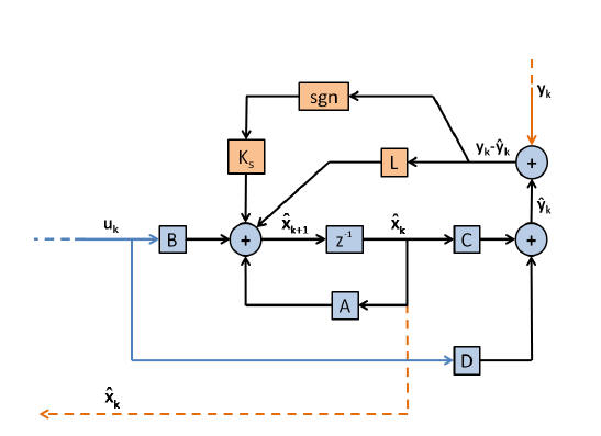
Figure 1. Proposed Structure of Robust Observer
We performed a simulation to evaluate the effectiveness of the proposed state estimation algorithms. A model of a single axis of a CAMotion three axis gantry style packaging robot (Fig. 2(a)) was developed using the assumed mode modeling technique described in section II. and the observer structures outlined in section III. were implemented using the LabView 2009 Control Design and Simulation Module. A linear quadratic regulator with penalties on cart position error, tip acceleration, and command effort was used as the controller. And for consistency all observers were evaluated using the same controller gains and standard industrial trapezoidal velocity profiles. Nonlinearities present in the physical system were implemented in the simulation, including saturation of the motor drives and dead-band. Likewise, noise characteristics from the system sensors, an angular encoder for cart position and a piezoelectric accelerometer for tip acceleration were measured and included. Possible sources of parameter variation including beam length, tip mass, cart mass, cart friction, and loss factor were identified and considered to examine the robustness of each estimator. Fig. 2(b) represents a sample simulation result from a trapezoidal move of
30 cm in 0:5 s with a +75% variation in tip mass. Akin to the added mass of an object picked up by the gripper of the robot, the results illustrate the inherent robustness problem with the Kalman filter, as well as the benefits and behavior of the nonlinear observers and their effects on the controlled system. The actual output in each case is represented by the dark blue line and the observer estimates of the output by the lighter grey line. It should be noted that with 0% parameter variation and ignoring the system nonlinearities, all three observer systems provide nearly identical performance. Aside from the observed chatter in the case of the SMO estimator, and the responses in each case remain stable. However, as the system nonlinearity and parameter variation increase, the result becomes immediately apparent. It is clear from Fig. 2(b). that the controlled system is unstable when using the Kalman filter observer for the given amount of parameter variation and nonlinearity. This is due to the divergence of the estimated from the true system state. Using the sliding mode observer, the system remains stable but with significant residual tip vibration from the chattering effect. The boundary layer sliding mode observer, however, stabilizes the system and reduces residual tip vibration by decreasing the chatter present in the SMO system.
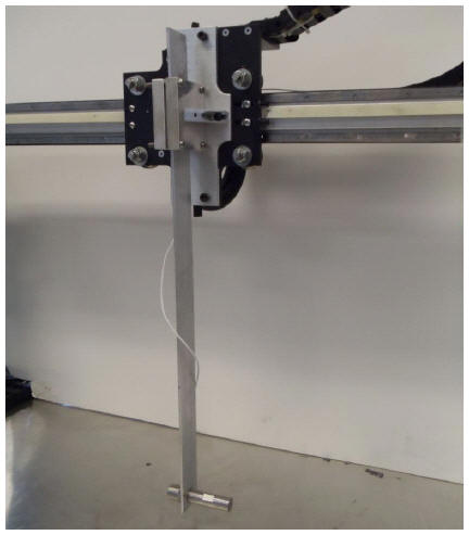
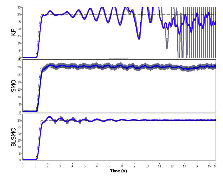
Figure 2. (a) Flexible Beam Manipulator (b) Simulation Results for a Point-to-Point Motion with 75% Tip Mass Variation
Researchers Involved
Brian K. Post – Graduate Student
Dr. Wayne Book – Faculty Advisor
JD Huggins – Research Engineer
Publications
Flatness-Based Control
Project Objectives
Flexible motion systems are prone to excessive and undesired vibration when operated near their performance limits. To mitigate these effects they are often operated well below their capable operating speeds. This not only limits the efficiency of these systems, but also hinders their functionality, as dexterity, performance, and workspace size are sacrificed for accuracy and reliability.
While feedback control yields performance improvements in vibration reduction and the ability to correct for external disturbances, errors between desired and ideal behavior must be measured before any control action is applied. Therefore, potential control structures should utilize reference command trajectories that result in a low level of undesired and potentially damaging vibration. In doing so, the utility of these systems can be expanded and the burden on reactive feedback control can be reduced.
While many motion systems are human operated in real time, like most industrial cranes and excavators, a large number use preprogrammed or repeated trajectories. For example, industrial robots used in manufacturing are often programmed to repeatedly perform the same motion. In some cases the control objective is to track a desired trajectory, for obstacle avoidance or efficiency. In other cases it is primarily to complete a motion by ending in the desired location. In either case, it is useful if the trajectory results in a reduction of both residual vibration and transient deflection.
We propose a method to generate trajectories for flexible motion systems with predetermined way-point targets. It is based on the differential flatness property of nonlinear systems and generates paths that result in both a reduction in residual vibration and transient deflection while enabling high-speed operation. This method is then applied to a tower crane in simulations and experiments aimed at accessing the effectiveness of the command generation approach to provide fast, vibration-limiting motions. The results are benchmarked against common command-shaping techniques.
Project Approach and Methods
Differential Flatness is a property akin to controllability of linear systems. It ensures the existence of a transformation from the desired output to a controlled variable. Flatness based control, is one method of inverse dynamics where a “flat output” is used to develop this mapping between output and input. The existence of a flat output means that the state x and input u can be directly expressed in terms of the output y and a finite number of its derivatives without the solution of a differential equation. Therefore, given a set of desired flat trajectories, command profiles can be directly determined that yield the desired output. As a result, if a flat trajectory is specified that has no oscillatory behavior, then the command produced by the mapping should result in no vibration. This, of course, relies on the assumption that every behavior of the dynamic system is modeled very accurately and that the system is capable of producing the command profiles.
This formulation produces additional constraints for the specification of the desired trajectories, most importantly that the trajectory must be continuous, at a minimum, to the highest order dynamic of the flat output. However, in the literature it is suggested that for a C2 dynamic system the specified trajectory be at least C4. Finally, at the initial and final position the successive derivatives must be zero.
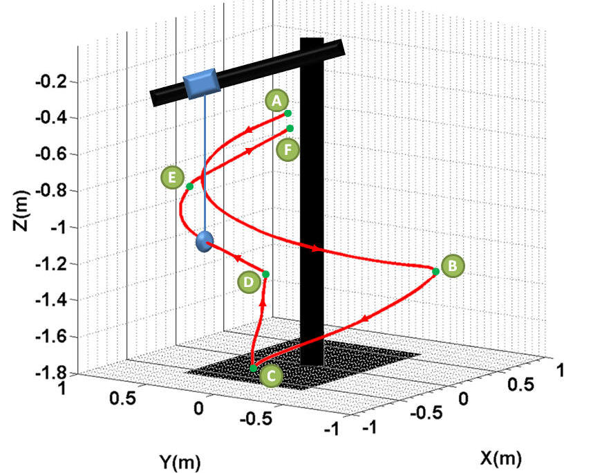
To satisfy these constraints a polynomial is traditionally generated whose coefficients are matched to the specific boundary conditions. However, this results in an S-curve like trajectory, which only reaches the maximum velocity at one instant in time. Thus, this approach can result in slow commands that hinder system performance.. Therefore, to define the trajectories used in this study, switching times for the acceleration profile of a jerk-limited command were calculated. Then, a third-order spline curve with the appropriate boundary conditions was fit to the desired acceleration to create a trajectory that satisfied all of the conditions for the flat output formulation.. This curve was then numerically integrated with a simple trapezoidal approximation and a 1 millisecond sampling rate to determine the velocity profile, and integrated again to determine the position trajectory. Once the trajectory was completely defined, the flatness-based control algorithm was executed to produce the desired commands. These commands were then checked against the performance capabilities of the motors and drives. If the commands violated the velocity or acceleration limits, then the design trajectories were modified by selectively reducing the aggressiveness of the desired motions. This procedure was carried out iteratively until the commands produced were within the capabilities of the system.
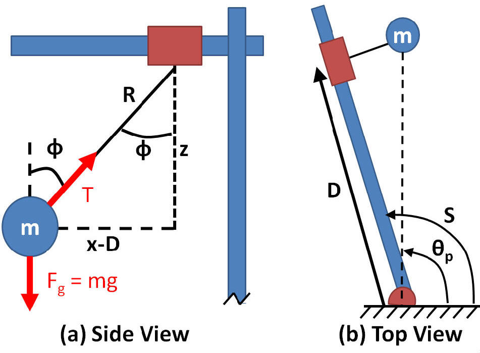
Figure 1. (a) Tower Crane Diagram (b) Generated Commands
To examine the effectiveness of the proposed method for a tower crane, a simulation was performed using standard command shapers as benchmarks. Figure 2(a) is a result of a simulation of the payload response to a 0
:21m point-to-point motion of the trolley using all four control methodologies: unshaped (US), ZV shaped, EI shaped and with the CAID controller (Flatness-Based Controller). It is immediately obvious that the ZV shaper, EI shaper, and CAID controller result in a drastic reduction in residual vibration of the payload when compared to the unshaped (trapezoidal velocity profile) case. These results show that for motion in the trolley axis with constant hoist length (1m), the ZV shaper and CAID controller perform the desired move in relatively comparable times, with the CAID controller slightly slower because the commands are moderately less aggressive. The EI shaper produces a significantly slower response. Also important to note is that while the ZV and EI shapers enforce conditions on the residual vibration, no direct attempt is made to minimize the payload sway during the move. In contrast, by specifying the position, velocity, and acceleration of the payload at every time step, the CAID controller results in less deflection during the move than the ZV shaper and faster move time than the EI shaper. The EI shaper does produce the lowest transient deflection, but at the cost of a 27% increase in execution time.While comparable to the ZV shaper in both speed and residual vibration for the single axis case, the benefit of the CAID method becomes more noticeable as the nonlinearities of the system are amplified by slewing and changing the hoist length. As illustrated by Figure 9, the overall effect of these methods is to place zeros in the vicinity of the flexible system poles reducing their effect in the response. The EI Shaper places a set of zeros above and below the vibratory poles resulting in a reduction of vibration for wide variations in natural frequency. However, the ZV shaper and CAID controller place zeros directly over the poles, effectively eliminating the oscillatory nature of the response, when the model is perfect. As the pole locations change, moving towards the real axis for increasing and away for decreasing hoist length, the ZV zero locations remain fixed, resulting in imperfect cancellation. The CAID zeros, however, attempt to track the changing poles. Figure 2(b) shows the residual oscillation of the payload for a 0
:53m trolley move, a 1:22m change in hoist length, and a 180 degree change in slew. The residual vibration in the radial direction is significantly lower with the CAID controller than either the ZV or EI shapers. In the tangential direction, the ZV shaper provides the smallest residual vibration. However, the magnitude of the residual vibration, as expressed by the norm of the maximum tangential and radial deflections, is significantly smaller for the CAID method.
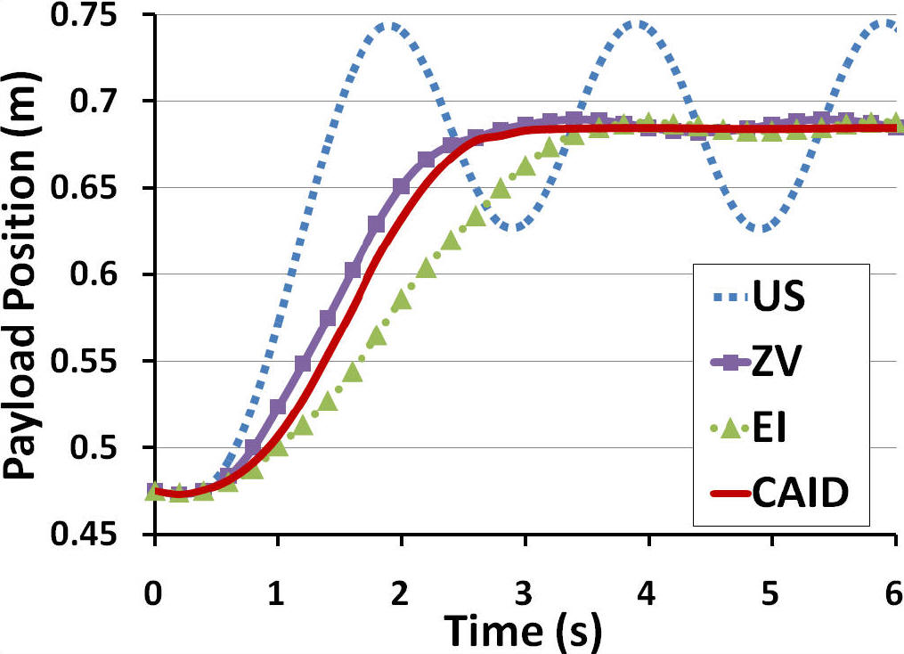
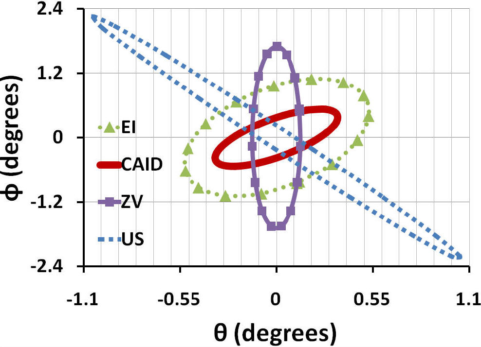
Figure 2. (a) Point-to-Point Response (Simulation) (a) Residual Vibration (simulation)
When a comparison is drawn between each of the techniques it is apparent that the CAID method provides a good combination of both speed and vibration reduction. ZV shaping results in comparably fast motions, but with increased residual vibrations when the nonlinearities become important. EI shaping creates trajectories with low residual vibration amplitudes for a wide range of conditions, but at the cost of slower operation.
Researchers Involved
Brian K. Post – Graduate Student
Dr. Wayne Book – Faculty Advisor
JD Huggins – Research Engineer
Publications
3. Post, B.K., et al., Flatness-Based Control of Flexible Motion Systems, in ASME Dynamic Systems and Controls Conference. 2011: Arlington, Virginia.